Casio Exilim EX-S500 Service Manual
Casio Exilim EX-S500 Service Manual
Casio Exilim EX-S500 Service Manual

You also want an ePaper? Increase the reach of your titles
YUMPU automatically turns print PDFs into web optimized ePapers that Google loves.
CONTENTSSPECIFICATIONS ....................................................................................................................................... 1BLOCK DIAGRAM ...................................................................................................................................... 5TEST MODE ................................................................................................................................................ 6PROGRAM VERSION UPGRADING .......................................................................................................... 71. To update the firmware version ..................................................................................................... 72. How to restore the firmware ........................................................................................................... 83. To install the firmware .................................................................................................................... 9ADJ TOOL ................................................................................................................................................. 101. Preparation ..................................................................................................................................... 102. How to use ADJ Tool when replacing Lens unit ........................................................................ 123. How to use ADJ Tool when replacing MAIN PCB ...................................................................... 13VCOM DC ADJUSTMENT ........................................................................................................................ 14CURRENT CONSUMPTION ..................................................................................................................... 17THE COUNTERMEASURE FOR "SYSTEM ERROR" ............................................................................. 17DISASSEMBLY ......................................................................................................................................... 18<strong>EX</strong>PLODED VIEW ..................................................................................................................................... 22PARTS LIST .............................................................................................................................................. 23PRINTED CIRCUIT BOARDS ................................................................................................................... 25SCHEMATIC DIAGRAMS ......................................................................................................................... 27
SPECIFICATIONSImage Files Format Snapshots: JPEG (Exif Ver.2.2); DCF (Design rule for Camera File system) 1.0 standard;DPOF compliantMovies: AVI (MPEG-4)Audio: WAVRecording Media8.3MB built-in flash memorySD Memory CardMultimediaCardImage Size Snapshots: 2560 x 1920 pixels2560 x 1712 (3:2) pixels2304 x 1728 pixels2048 x 1536 pixels1600 x 1200 (UXGA) pixels640 x 480 (VGA) pixelsMovies: 640 x 480 pixelsApproximate Memory Capacity and File sizes• SnapshotsFile Size(pixels)QualityApproximate ImageFile SizeBuilt-in flash memory8.3 MBSD Memory Card*256 MB2560 x 19202560 x 1712(3:2)2304 x 17282048 x 15361600 x 1200(UXGA)640 x 480(VGA)FineNormalEconomyFineNormalEconomyFineNormalEconomyFineNormalEconomyFineNormalEconomyFineNormalEconomy3.0 MB2.0 MB1.0 MB2.85 MB1.9 MB950 KB1.95 MB1.53 MB800 KB1.64 MB1.23 MB630 KB1.05 MB710 KB370 KB190 KB140 KB90 KB2 shots3 shots7 shots2 shots4 shots7 shots4 shots5 shots9 shots4 shots6 shots11 shots7 shots10 shots20 shots38 shots50 shots79 shots80 shots118 shots226 shots84 shots124 shots237 shots124 shots153 shots277 shots138 shots184 shots356 shots215 shots319 shots623 shots1187 shots1557 shots2491 shots* Based on Matsushita Electric Industrial Co., Ltd. products.Capacity depends on card manufacturer.* To determine the number of images that can be stored on a memory card of a different capacity, multiply the capacitiesin the table by the appropriate value.• Movies (640 x 480 pixels)Data Size4.1 MB /second max.— 1 —
DeleteSingle-file, all files (with protection)Effective Pixels5.0 millionImaging Element1/2.5-inch square pixel color CCD (Total pixels: 5.25 million)Lens/Focal Distance Lenses F2.7 (W) to 5.2 (T); f=6.2 (W) to 18.6mm (T) (equivalent to approximately 38 (W)to 114mm (T) for 35mm film)6 lenses in 5 groups, with aspherical lensZoom3X optical zoom; 4X digital zoom (12X in combination with optical zoom)FocusingContrast Detection Auto FocusFocus Modes: Auto Focus, Macro mode, Pan Focus, Infinity mode, manual focusAF Area: spot, multi; AF Assist LightApproximate Focus Range Auto Focus : 40cm to ∞ (1.3´ to ∞)(from lens surface) Macro : 17cm to 50cm (6.7˝ to 19.7˝)Infinity Mode : ∞<strong>Manual</strong> : 17cm to ∞ (6.7˝ to ∞)• Using optical zoom causes the above ranges to change.Exposure Control Light Metering : Multi-pattern, center-weighted, spot by CCDExposure: Program AEExposure Compensation : –2EV to +2EV (1/3EV units)ShutterCCD electronic shutter; mechanical shutterSnapshot mode (Auto): 1/8 to 1/2000 second• Above shutter speeds do not apply when using a BEST SHOT scene.ApertureF2.7/4.3, auto switching• Using optical zoom causes the aperture to change.White BalanceAuto WB, fixed (6 modes), manual switchingSensitivity Snapshots : Auto, ISO 50, ISO 100, ISO 200, ISO 400Movies : AutoSelf-timer10 seconds, 2 seconds, Triple Self-timerBuilt-in FlashFlash Modes :Auto Flash, ON, OFF, Red eye reductionFlash Range : Wide Angle Optical Zoom: 0.4 to 2.8 meters (1.3´ to 9.2´)Telephoto Optical Zoom : 0.4 to 1.4 meters (1.5´ to 4.6´)(ISO Sensitivity: “Auto”)* Depends on zoom factor.Recording Functions Snapshot; audio snapshot; macro; self-timer; Continuous shutter; movie with audio (NormalMovie, Short Movie, Past Movie); Voice Recording; BEST SHOT mode (scenes other thanShort Movie, Past Movie, and Voice Recording)• Audio recording is monaural.Audio Recording Time Audio Snapshot : Approximately 30 seconds maximum per imageVoice Recording : Approximately 25 minutes with built-in memoryAfter Recording : Approximately 30 seconds maximum per imageMonitor Screen2.2-inch TFT color LCD84,960 pixels (354 x 240)ViewfinderMonitor screenTimekeeping Functions Built-in digital quartz clockDate and Time : Recorded with image dataAuto Calenda : To 2049World Time : City; Date; Time; Summer time;162 cities in 32 time zonesInput/Output Terminals Cradle connectorUSBUSB 2.0 Hi-Speed compatibleMicrophoneMonauralSpeakerMonaural— 2 —
Power RequirementsPower Requirements Rechargeable lithium ion battery(NP-20) x 1Approximate Battery Life:The values below indicate the amount of time under the conditions defined below, until power automatically turns off due to batteryfailure. They do not guarantee that you will be able to achieve this level of operation. Low temperatures shorten battery life.OperationNumber of Shots (CIPA Standard)* 1(Operating Time)Number of Shots, Continuous Recording* 2(Operating Time)Continuous Snapshot Playback* 3Continuous Movie Recording* 4Continuous Voice Recording* 5Apporoximate Battery Life200 shots(100 minutes)410 shots(100 minutes)160 minutes80 minutes160 minutesSupported Battery : NP-20 (Rated Capacitance: 700mAh)Storage Medium : SD Memory Card*1 Number of Shots (CIPA Standard)• Temperature: 23°C (73°F)• Monitor Screen: On• Zoom operation between full wide to full telephoto every 30 seconds, during which two images are recorded, one imagewith flash; power turned off and back on every time 10 images are recorded.*2 Continuous Recording Conditions• Temperature: 23°C (73°F)• Monitor screen: On• Flash: Off• Image recorded every 15 seconds, alternating full wide-angle and full telephoto zoom*3 Continuous Snapshot Playback Conditions• Temperature: 23°C (73°F)• Scroll one image about every 10 seconds*4 Approximate time for continuous movie recording, without using zoom.*5 Voice recording times are based on continuous recording.Power Consumption 3.7V DC Approximately 3.2WDimensions90(W) x 59(H) x 16.1(D) mm(3.5˝(W) x 2.3˝(H) x 0.63˝(D))(excluding projections; 13.7 mm (0.54˝) at thinnest part)WeightApproximately 115 g (4.1 oz) (excluding battery and accessories)Bundled Accessories Rechargeable lithium ion battery (NP-20); USB cradle (CA-28); Special AC adaptor; ACpower cord; USB cable; AV Cable; Strap; CD-ROMs (2); Basic Reference— 3 —
Rechargeable Lithium Ion Battery (NP-20)Rated VoltageRated CapacitanceOperating TemperatureRangeDimensionsWeight3.7 V700 mAh0°C to 40°C (32°F to 104°F)33(W) x 50(H) x 4.7(D) mm (1.3˝(W) x 2.0˝(H) x 0.19˝(D))Approximately 16 g (0.56 oz)USB Cradle (CA-28)Input/Output Terminals Camera connector; USB port; AC adaptor terminal (DC IN 5.3V) /AV output port (Special mini port, NTSC / PAL)Power Consumption 5.3V DC Approximately 3.2WDimensions112(W) x 24(H) x 58(D) mm (4.4˝(W) x 0.94˝(H) x 2.3˝(D)) (excluding projections)WeightApproximately 52 g (1.8 oz)Special AC Adaptor (Inlet Type) (AD-C51G or AD-C52G)Power RequirementOutputDimensionsWeight100 to 240V AC, 50/60Hz, 83 mA5.3V DC, 650 mAAD-C51G: 78(W) x 20(H) x 39(D) mm (3.1˝(W) x 0.8˝(H) x 1.5˝(D))(excluding projections and cable)AD-C52G: 50(W) x 20(H) x 70(D) mm (2.0˝(W) x 0.8˝(H) x 2.8˝(D))(excluding projections and cable)AD-C51G: Approximately 90 g (3.2 oz)AD-C52G: Approximately 87 g (3.1 oz)Special AC Adaptor (Plug-in Type) (AD-C51J or AD-C52J)Power RequirementOutputDimensionsWeight100 to 240V AC, 50/60Hz, 83mA5.3V DC, 650mAAD-C51J: 48(W) x 16(H) x 69(D) mm (1.9˝(W) x 0.6˝(H) x 2.7˝(D))(excluding projections and cable)AD-C52J: 50(W) x 18(H) x 70(D) mm (2.0˝(W) x 0.7˝(H) x 2.8˝(D))(excluding projections and cable)AD-C51J: Approximately 91 g (3.2 oz)AD-C52J: Approximately 85 g (3.0 oz)Power Supply• Use only the special NP-20 rechargeable lithium ion battery to power this camera. Use of any other type of battery is notsupported.• This camera does not have a separate battery for the clock. The date and time settings of the camera are clearedwhenever power is totally cut off (from both the battery and USB cradle). Be sure to reconfigure these settings afterpower is interrupted.LCD Panel• The LCD panel is a product of the latest LCD manufacturing technology that provides a pixel yield of 99.99%. This meansthat less than 0.01% of the total pixels are defective (they do not turn on or always remain turned on).Lens• You may sometimes notice some distortion in certain types of images, such as a slight bend in lines that should bestraight. This is due to the characteristics of lens, and does not indicate malfunction of the camera.— 4 —
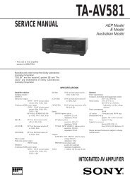
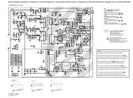
— 5 —BLOCK DIAGRAMSStrobeStrobeKeyKeySDSDVideoVideoCradleCradlePowerPower8bit8bitMCMMCMAudioAudioLCDLCDCCDCCDMotorMotor8bit-MICONUPD78F8011F1AQ1E2ANECIC400R8J30214AEBGVRenesasAudio_ICAK4631VG- LVIDEO_AMPNJW1331KK1JRCMotor_drM63069HP-DF0TRenesasV_drML9711HAZ03BOKISWSWSDIC104LDOIC105SDIC102GNDGNDBAT+BAT-LDOIC103SUIC101LDOIC100AFEHD49346BP-ERenesasSD2StrobeCN803(10PIN)VCC1-0VCC5-2CENDNCENDNCHGIGBTCNTCHGIGBTCNTPOWSWSHUTSWHALFSHUTKIN1KIN2KIN3KEY CN801(17PIN)2236KEYAF_LEDLEDSPEAKERSPPSPNR-LEDG-LEDSELFLEDAFLED_AAFLED_CEVCC3.3discretediscreteSDDAT0SDDAT1SDDAT2SDDAT3SDCMDSD CN800(15PIN)VCC3.3D52SDCDSDWPSDCLKVIDEOVA_STBYVCC3.3AVOUT2432CradleCN802(30PIN)BATTEMPCHGCTLMONOOUTVOUTAVDETVBUSKIN4D+D-DCCHGVCCGNDdiscreteTHTHVCC1-1VCC1-2VCC1-0VCC1-1VCC1.2VCC1.8VCC5-1VCC5-1VEE7.5VCC15VCC15CVEE7.5CPWCTL2PWCTL1VCC5-2VCC3.3DVCC1-2VCC3.3AEVCC3.3PWCTL0PWCTL4PWCTL3PWCTL52chDC/DCIC1079SP0103NC3-3SPPSPNMONOOUTMCKOBICKLRCKSDTOSDTICDTICCLKCSNPDNMICVCC3.3A48MHzVCC1.8VCC1.2VCC3.3DVCC3.3AVCC5-23discretediscretediscretediscretediscretediscreteVSSLCD-FPCVCC15VCC3.3DCTL_SIGV/H_SYNCCLK(6.75MHz)DATACOMOUTVCOMBLON326P110BLLEDAP111BLLEDKBLONVCC15VCC15VCC15VCC3.3DVCC5-2EVCC3.3VBUS32KHzVCC1-1VCC5-1VCC3.3CVEE7.5VCC3.3DCN600 (33pin)LCDCLKVSYNCHSYNCLCDO1LCDCSLCDSCKLCDAT2LCDAT3LCDAT4LCDAT5LCDAT6LCDAT7BLPWMBL14CCD-FPCCN200 (27pin)3198122VCC15VEE7.5V_SIGVSUBCCDINH_SIGCSUBPWCTL5CTLOFDC_1OFDC_2CDDAT[0:12]THLENS-FPCCN500 (25pin)IRIS/SHUTZOOMFOCUSVCC_PIZM_ENC_LEDZM_ENCZM_HOME_LEDZM_HOMEAF_HOME_LEDAF_HOME4210+-4Z_ENC_DETF_HOME_LEDLENS_THZ_HOME_DETF_HOME_LEDF_HOME_DETMT_STBMT_SCKMT_DATAZOOM0FOCUS0FOCUS1FOCUS2IRIS0IRIS1IRIS2PWCTL0PWCTL1PWCTL2PWCTL3PWCTL4PWCTL5FOUTPSRDYCHGCTLAFLED_APSOUTRESETBBATTEMPKINTBWKUPBSHUTTER2STBYBPSCKPSINPSRESETBTHADPINPDWSWSHUTSWHALFSGUTKIN1KIN2KIN3KIN4166KEY 7BATTERY
TEST MODENote: Never perform the menu items unless otherwise instructed. Doing so may cause destruction ofthe data inside, which will make the camera unusable.■ To boot the test mode1. While firmly pressing down both [BS], [PW ON] and [UPPER], turn the power on.[UPPER] button[BS] button2. After the version appears, press buttons in the order of [DOWN], [DOWN], [BS] and [MENU] in 0.5second. The diagnostic menu appears.[DOWN] button++ KX835 ++Ver 1.02[MENU] button[BS] button"DOWN" button -> "DOWN" button -> "BS" button -> "MENU" button1 :VERSION INFO2 :USB TCC TEST3 :ROM UPDATE4 :LAST MEMORY5 :FORMAT"SET" button1 :USB TCC ON2 :USB TCC OFF3 :USB STORAGE4 :USB SPEED"MENU" button— 6 —
PROGRAM VERSION UPGRADING1. To update the firmware version1. Prepare the memory card which contains the firmware for <strong>EX</strong>-<strong>S500</strong> in the root directory.<strong>EX</strong>-<strong>S500</strong>.bin2. Insert the above memory card into the camera, and set a fully charged battery in the camera.3. Press the [power button] while holding [MENU] depressed. Keep holding [MENU] depressed until“PROGRAM UPDATE” appears in the display.• The following appears.• The version of the firmware in the memory card appears at the bottom of the display.PROGRAM UPDATEYESNONEW VERSION ISVER 1.02(As of Dec 2005)NOTE 1) When a wrong software is mistakenly used,the message below appears. Update thefirmware again with the correct software.FILE ERROR!NOTE 2) When only the version appears in the displayeven though you are trying to operate thecamera, charge the battery to the fullest andtry again. The level of the battery indicatorshould be highest in order to update thefirmware.4. Align the white cursor to [YES] by [UPPER] and [DOWN], and then press [SET].• “NOW LOADING” appears in the display and the update starts.5. “COMPLETE” appears after the update finishes.6. Remove the memory card after turning the power off once. Turn the power back on again while holding[MENU] depressed, and check the version.• “VER.1.02” appears.VER 1.02(As of Dec 2005)7. If the version is correct, turn the power off.8. Finally, check the operation by recording, playing back and deleting an image.— 7 —
2. How to restore the firmware1. Prepare the firmware restoration program and change its name as follows;rom835_051122.lbn saturn.binNOTE: This software and procedure automatically restores the firmware even if the firmware belongsto a wrong model code. Make sure to use the correct software for the correct model.2. Copy the above file to the root directory in the memory card.3. Insert the memory card into the camera.4. Set a fully charged battery in the camera.NOTE: This software and procedure automatically restores the firmware even if the battery capacity ofthe camera is low. Make sure to use a fully charged battery to prevent the danger of powerdown during firmware restoration.5. Turn the power on while pressing the [shutter release] button.If the power does not turn on only by pressing the power button, insert the battery while holding the[shutter release] button depressed.• The LED next to the optical viewfinder changes from “green/red blinking”, “green blinking” to “greensteady”.NOTE: This software and procedure automatically restores the firmware even if the firmware belongsto a wrong model code. Make sure to use the correct software for the correct mode.6. When the LED becomes “green steady”, the firmware restoration is finished.Remove the battery and the memory card, and then turn the power off.7. Turn the power on again while holding [BS] and [UPPER] depressed.Check the model name and the program version (PR:) in the opening screen of the test menu.++KX835++Ver 1.028. If the model name and the program version are correct, perform SYSTEM INITIAL to initialize thesystem area.“BS + UPPER + PW ON” “DOWN, DOWN, BS, MENU” “3:ROM UPDATE” “5:SYSTEM INITIAL”NOTE: After SYSTEM INITIAL is performed, “SYSTEM ERROR” appears when the power is turnedon again.9. Write the latest firmware. (Refer to page 6)After the firmware is written, check the model name and the program version (PR:) in the openingscreen of the test menu.10. Finally, start the camera normally to check the operation by recording, playing back and deleting animage. Check also that the colors in the images are not too bright or two dark.— 8 —
3. To install the firmwareInitially, firmware is not installed in the PCB supplied by the parts center.Install the firmware into the PCB after replacing with a new one as shown in the procedures below.Note: The camera does not operate (only LED becomes “green blinking”) if the firmware is not installed inthe PCB.1. Copy the following software to the root directly of the SD card.Restoration software: rom835_051122.lbnFirmware:<strong>EX</strong>-<strong>S500</strong>.bin2. Change the name as follows;“rom835_051122.lbn” to “saturn.bin”3. Insert the SD card into the camera.4. Insert the battery while holding the [shutter release] button depressed.The LED next to the optical viewfinder changes from “green/red blinking”, “green blinking” to “greensteady”.5. When the LED becomes “green steady”, remove the battery and turn the power off.1. Boot the test mode.2. Press [DOWN] twice and then press [BS], [MENU].3. Select “3: ROM UPDATE” and then press [SET].4. Select “5: SYSTEM INITIALIZE” and then press [SET].5. When the following message appears, press [SET].SYSTEM INITIALIZESTART….PUSH OK KEY?6. The system initialize is executed. Turn off the power when “SUCCESS” appears.* “SYSTEM ERROR” appears when the camera is turned off without system initialize.1. Turn the power on while holding [MENU] depressed.2. When “PROGRAM UPDATE” appears, select “YES” and then press [SET].3. “NOW LOADING” appears while the firmware is updated.4. When “COMPLETE” appears, the firmware update is complete.5. Turn the power on and off to check if the camera normally functions. If there is no problem, the firmwareupdate is successful.— 9 —
ADJ TOOL■ IntroductionMake sure to perform the adjustment by the USB ADJ Tool “adj03SSAW.exe” when replacing the lens unitor the PCB.Here the necessary software, driver and setting are explained to use “adj03SSAW.exe”.Note that the tool, drivers etc. are available only for Windows.1. Preparation1-1. Prepare the necessary software, driver and DLL file.1) Prepare the following three files.• Testmode driver[testmode_driver] folderuusbd.dlluusbd.infuusbd.sys* testmode_driver_2.0] is for Windows except Windows98.* [testmode_driver] is for Windows98 only.• ADJ tool, USB DLL and ADJ setting file[adj03SSAW] folderadj03SSAW.exe (ADJ tool itself)uusbd.dll (USB DLL)* .adt (ADJ setting file. Sorted by models)2) Place the testmode driver in an appropriate place.3) Place all of ADJ tool, USB DLL and ADJ setting file in the same folder.1-2. Set the camera so that it recognizes the USB test mode.1) Enter the test menu.Turn the power on while pressing both [BS] and [UPPER].Press [DOWN], [DOWN], [BS] and [MENU].2) Move the cursor to “2: USB TCC TEST” and press [SET].3) Move the cursor to “1: USB TCC ON” and press [RIGHT], [RIGHT] and [SET].4) USB TCC ON is now active. Turn the power off.5) The test menu appears first when the camera power is turned on.* When changing the USB TCC ON to OFF, set “2: USB TCC OFF” in the test menu.1-3. Install the USB driver for the USB test mode in the computer.(The following is an example using the Windows Me.)1) Prepare the USB driver for the USB test mode.2) Turn the camera power on which is set in the USB test mode as shown in 1-2 and let it enter the USBtest mode directly (the test menu appears right after the power is turned on).3) Connect the camera in the above status to the computer by the USB cable.4) The “Add new hardware” wizard appears.5) Check “Designate the place for the driver (for users with sufficient knowledge)” and press “Next”.6) Check “Search for the optimum driver for the device (recommended)”.— 10 —
7) Check “Designate the place to search”, designate the place which contains “inf” file in the driver bypressing “Reference” button, and then press “Next” button.8) When “Universal USB Driver (VMEM manufacturer’s name)” appears upon message “Searching forthe driver file for the following devices”, press “Next” button.9) The file copy starts.(If a message “uusbd.inf cannot be found” appears during the file copy, designate the same place asin the step 7).10) Press “Complete” button.11) Right-click “My computer”, select “property”, and then open “Device manager”.If “Universal USB Driver (VMEM manufacturer’s name)”,“USB device for UUSBD” can be found, thecomputer has successfully recognized the driver.12) Installing the test driver into either one enables the other one to recognize it.* How to uninstall the USB driver for the USB test mode• Connect the camera to the computer while in the USB test mode so that the computer recognizesthe camera.• Right-click “My computer”, select “Property” and open “Device manager”.• Select “USB device for UUSBD” , and then “Universal USB Driver (VMEM manufacturer's name)”.• Press “Delete” button to delete the driver.• When using Windows98/98SE/Me, delete the following three files;(NOTE! Do NOT delete “usbd.inf” and “usbd.sys”, whose names are much alike the following.)C:windows / inf / uusbd.infC:windows / inf / other / KashiwanoUUSBD.infC:windows / system32 / drivers / uusbd.sys• The driver has been successfully deleted.1-4. Use the USB ADJ Tool1) Prepare ADJ tool, USB DLL and ADJ setting file in the same folder.2) Turn the camera power on which is set in the USB test mode and let it enter the USB test mode directly(the test menu appears right after the power is turned on).3) Boot “adj03SSAW.exe” and use it as follows;• To read ADJ data from the camera Press “READ ($9)”.There is no neto set the model by “FW Item Set”.• To write ADJ data into the camera Press “WRITE ($8)”.• To save ADJ data which is read Select “File” and “Save All ADJ”, and save it under an appropriate name.• Open ADJ data which is saved 1. Select the model by "FW Item Set", and then press "Load FW ->" button.2. Select “File” and “Open”, and open the necessary file.• Language” radio button can switch the language between Japanese and English in which the nameof the ADJ ITEM is displayed.• “Radix” radio button can switch the data display between decimal and hexadecimal notations.— 11 —
2. How to use ADJ Tool when replacing Lens unitMake sure to perform the following procedure after replacing the lens.A floppy disk with the lens data is bundled in the spare parts of the lens unit.How to enable USB TCC ON is the same as <strong>EX</strong>-Z750.1 Enter the TEST mode.1. Turn the power on while pressing both "BS" and "UP" buttons.2. Press "DOWN" button, "DOWN" button, "BS" button, and "MENU"button while the program version is displayed.3. Select "2.USB TCC TEST", and press "SET" button.4. Select "1. USB TCC ON", and press "RIGHT" button, "RIGHT" buttonand "SET" button.5. Turn the power OFF.2 Connect the camera to the computer by the USB cable.3 Boot "adj03ssaw" .4 Select the model name and click "Load FW " Key.• <strong>EX</strong>-<strong>S500</strong>5 Click "ADJ ALL READ", and display the data on the "adj03ssaw".6 Find the No.1163, "LCD VCOM DC".7 Write down this value(data).8 Replace the Lens unit.9 Perform the above 1 to 3.0 Select the model name and click "Load FW " Key.• <strong>EX</strong>-<strong>S500</strong>A From "File/Open", open the bundled floppy disk, and transfer the data tothe "adj03ssaw".AB Find the No.1163,"LCD VCOM DC"C Change the data to the former value.(Refer to 7).D Click "WRITE" button of "ADJ ALL".E After adjustment, change "1. USB TCC ON" to "2. USB TCC OFF".64D— 12 —
3. How to use ADJ Tool when replacing MAIN PCBFirmware is not installed in spare parts.1 Enter the TEST mode.1. Turn the power on while pressing both "BS" and "UP" buttons.2. Press "DOWN" button, "DOWN" button, "BS" button and "MENU"button while the program version is displayed.3. Select "2.USB TCC TEST", and press "SET" button.4. Select "1. USB TCC ON", and press "RIGHT" button, "RIGHT" buttonand "SET" button.5. Turn the power OFF.2 Connect the camera to the PC by the USB cable.3 Boot "adj03ssaw".4 Select the model name and click "Load FW " Key.• <strong>EX</strong>-<strong>S500</strong>5 Click "ADJ ALL READ", and display the data on the "adj03ssaw".6 Save the data.7 Replace the MAIN PCB.8 Writing the Firmware.Write the firmware into a spare part after replacing one.NOTE: If a battery is inserted without the firmware, only LEDblinks green and the camera does not operate.9 Perform the above 1 to 3.0 Select the model name and click "Load FW " Key.• <strong>EX</strong>-<strong>S500</strong>A Open the file which is saved above, and display the data on the"adj03ssaw".B Click "WRITE" button of "ADJ ALL".C After adjustment, change "1. USB TCC ON" to "2. USB TCC OFF".654AB— 13 —
VCOM DC ADJUSTMENT■ PurposeReadjust the VCOM value to minimize the flicker of the LCD after replacing the LCD or the main PCB.■ Necessary tools1. Camera (Charge its battery fully)2. Photo diode (S2281-01) : See Fig 1.3. Photo sensor amp (C2719) : See Fig 2.4. BNC-BNC cable (E2573) x 2 : See Fig 3.5. 9-volt alkaline battery (6LR61Y) x 2 : See Fig 4.6. Oscilloscope■ Preparation1. The three tools can be obtained from the following global site.Photo diode (S2281-01)Photo sensor amp (C2719)BNC-BNC cable (E2573)www.hamamatsu.com/2. 9-volt alkaline battery is a standard one, but can be obtained from the following global site as well.www.panasonic.co.jp/global/Fig1 Photo Diode (S2281-01)Fig2 Photo Sensor Amp (C2719)Fig3 BNC-BNC Cable (E2573)Fig4 6LR61Y— 14 —
■ Procedure1. Camera settinga) Turn the power on while pressing “BS” and “UPPER”.After pressing “DOWN” key twice, press “BS” and “MENU”.Select "2:USB TCC TEST", and press "SET" button.Select "1:USB TCC ON", and press "RIGHT" button ,"RIGHT"button and "SET" button.Figure (a) appears.Figure (a)1: VERSION INFO2: USB TCC TEST3: ROM UPDATE4: LAST MEMORY5: FORMAT6: HARD TEST7: IMAGE TEST8: ADJ TEST9: TEST SCRIPTb) Select “8 : ADJ_TEST” and then press SET.(See Figure (b).)Figure (b)1: ADJ STAT CLR2: LCD3: LENS...c) Next, select “2. LCD” and then press SET.(See Figure (c).)Figure (c)1:VCOM...OKd) Pressing SET causes the right figure to appear.(See Figure (d).)Figure (d)OK -> Register WriteVCOM = 0xcaThis value is an example and differs by products2. Connecting the TOOLa) Place two 9-volt alkaline batteries in C2719.b) Connect the output terminal of C2719 to the channel terminal of the oscilloscope by the BNC-BNCcable.c) Connect the input terminal to the Photo Diode by the BNC cable.d) Turn the oscilloscope and C2719 on.* Pull the ON/OFF switch of C2719 this way and raise/lower it. (See below Figure.)— 15 —
3. Measurementa) Connect S2281-01 to the camera’s LCD monitor (see below).AC Waveforms appear on the monitor screen of the oscilloscope.* Change the Rf range of C2719 in case the range does not match.Photo diodeS2281-01INPUTPhoto sensor ampOUTPUTOscilloscopeCAMERABNC-BNC cableLCDMinimize theripple componentsb) After AC waveforms of the oscilloscope appear, minimize it by pressing the camera’s up/down buttons(see the picture).Make sure to visually check if it has been minimized.[UPPER] button[DOWN] buttonAfter it has been minimized, press SET key.The screen in the right figure appears and the new VCOM iswritten (VCOM adjustment is finished.).OK -> Register WriteVCOM = 0xcaADJ DATA SET!Return to the previous display by pressing MENU or PW key.This value is only an example, and differs by products.— 16 —
CURRENT CONSUMPTION(1) Current consumption (DC in = 3.70 ± 0.1 [V])• Make sure that current consumption is less than 250 mA in PLAY mode.• Make sure that current consumption is less than 360 mA in REC mode.• Make sure that current consumption is less than 160 µA when power is turned OFF.(2) The battery indicator changes according to the voltages as follows.• DC in = less than 3.76 ± 0.05 V: (PLAY mode)• DC in = less than 3.66 ± 0.05 V: (PLAY mode)• DC in = less than 3.51 ± 0.05 V: (PLAY mode)THE COUNTERMEASURE FOR "SYSTEM ERROR"System error may occur when the battery is removed while data is written to the internal memory.■ PROCEDURE1. Initialize the system.a) Enter the TEST mode.b) Select "3:ROM UPDATE" and press SET button.c) Next, select "5:SYSTEM INITIAL" and press SET button.d) The following message appears.SYSTEM INITIALIZESTART ...PUSH OK KEY?e) Press SET button and System is initialized."SUCCESS !" appears on the monitor.2. Write firmware.Refer to the "1. To update the firmware version" on page 7.Write the firmware.If the TEST mode boots automatically, change "USB TCC ON" to "USB TCC OFF".Replace the Main PCB if the camera does not recover.— 17 —
DISASSEMBLY■ To remove the case1. Remove the battery.2. Remove six screws.Note: Make sure to use correct screws when assembling since there are two kinds of them.Make sure not to lose the strap.StrapScrews (S1)Screw (S2)Screw (S1)Screw (S1)3. Remove the front and rear panels.Front panelRear panel■ To remove the battery cover and the battery case assy4. Remove the battery, the battery cover and the battery case assy.Screw— 18 —
5. Separate the battery cover and the battery case assy.Battery case assy21Battery cover■ To Remove the main PCB and the LCD unit6. Remove one screw and four connectors, and then unsolder five lead wires.Precautions during assembly: Make sure the connectors are fitted completry.BlueYellowScrewGrayRedBlackConnectors7. Remove the main PCB and the LCD unit.8. Remove the connector, and separate the main PCB and the LCD unit.ConnectorPrecautions during assembly: Lace two lead wires through the B-FRAME.— 19 —
9. Remove the switch unit.The switch unit is fixed by two-sided tape.Switch unitTips during assembly: Fixing position■ To remove the strobe unit.10. Release the hook and then remove the strobe unit.Hook21— 20 —
■ To remove the lens unit.11. Release two hooks and then remove the lens unit.HookHookHooks■ To remove the tripod screw.12. Release two hooks and then remove the tripod screw.Hooks— 21 —
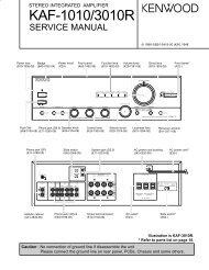
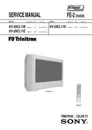
<strong>EX</strong>PLODED VIEW1S32451-21-1S5 ✕531-36-16S187101196-2S11412S2S1131817161915202122S42324— 22 —
PARTS LISTN ItemPartsQTYPriceParts NameSpecificationCode Gray Orange White CodeR RemarkN 1 10203433 CASE ASSY/FRONT TK-RJK507774*001 1 0 0 CS CN 1 10203434 CASE ASSY/FRONT TK-RJK507774*002 0 1 0 CS CN 1 10203435 CASE ASSY/FRONT TK-RJK507774*003 0 0 1 CW C1-1 10212798 GRIP BASE/A RJK507690-001V02 0 1 0 C1-1 10212799 GRIP BASE/B RJK507690-002V02 1 0 1 C1-2 10200753 GRIP/A RJK507689-001V01 1 0 1 C1-2 10200762 GRIP/B RJK507689-002V01 0 1 0 C1-3 10200752 CAM RING RJK507657-001V01 1 1 1 CN 2 10203451 PCB ASSY/MAIN RJK507669*001 TK 1 1 1 DV AN 3 10200795 TAPE RJK507766-001V01 1 1 1 AB XN 4 10200803 RUBBER/MIC RJK507722-001V01 1 1 1 AA CN 5 10203454 LENS UNIT RJK507772*001 TK 1 1 1 DY A *1N 6 10203436 CASE ASSY/REAR TK-RJK507775*001 1 0 0 CM CN 6 10203437 CASE ASSY/REAR TK-RJK507775*002 0 1 0 CM CN 6 10203438 CASE ASSY/REAR TK-RJK507775*003 0 0 1 CQ C6-1 10200785 KEY/A HKW1528-020010 1 0 0 C6-1 10200821 KEY/A HKW1528-020020 0 1 0 C6-1 10200788 KEY/A HKW1528-020030 0 0 1 C6-2 10200818 KEY/B HKW1528-030010 1 1 0 C6-2 10200791 KEY/B HKW1528-030020 0 0 1 CN 7 10200774 STRAP BASE RJK507719-001V01 1 1 0 AJ CN 7 10200745 STRAP BASE RJK507719-002V01 0 0 1 AJ CN 8 10203445 SW BLOCK TK-RJK507780*001 1 0 1 BY CN 8 10203447 SW BLOCK TK-RJK507780*002 0 1 0 BZ CN 9 10200806 TAPE RJK507751-001V01 1 1 1 AB XN 10 10200800 SPRING/BATTERY RJK507791-001V01 1 1 1 AA CN 11 10203439 CASE ASSY/STROBE TK-RJK507777*001 1 1 1 CH CN 12 10203449 LCD ASSY TK-RJK507782*001 1 1 1 DE BN 13 10200804 TAPE RJK507739-001V01 2 2 2 AB CN 14 10200734 FRAME ASSY/BATTERY RJK507726*001V01 1 1 1 AP XN 15 10200802 SOCKET/TR RJK507718-001V01 1 1 1 AH XN 16 10203440 CASE ASSY/BATTERY TK-RJK507779*001 1 0 0 AM CN 16 10203442 CASE ASSY/BATTERY TK-RJK507779*002 0 1 0 AM CN 16 10203444 CASE ASSY/BATTERY TK-RJK507779*003 0 0 1 AM CN 17 10200825 CASE/BATTERY RJK507714-001V01 1 0 0 AC CN 17 10200829 CASE/BATTERY RJK507714-002V01 0 1 0 AC CN 17 10200830 CASE/BATTERY RJK507714-003V01 0 0 1 AC CN 18 10200826 SHAFT/BATTERY RJK507735-001V01 1 1 1 AA CN 19 10200827 SPRING/BATTERY RJK507792-001V01 1 1 1 AA CN 20 10170561 KNOB/BATTERY RJK506460-001V01 1 1 1 AB CN 21 10200773 BRACKET ASSY/BATTERY RJK507707*001V01 1 1 1 AE CN 22 10200828 SPRING/BATTERY RJK507793-001V01 1 1 1 AA CN 23 10200737 COVER/BATTERY RJK507713-001V01 1 0 0 AM CN 23 10200739 COVER/BATTERY RJK507713-002V01 0 1 0 AM CN 23 10200750 COVER/BATTERY RJK507713-003V01 0 0 1 AM CN 24 10204624 LABEL/RATING RJK507767-003V01 1 0 0 AF X For US/ EU/UKN 24 10204625 LABEL/RATING RJK507767-004V01 1 0 0 AF X Except US/ EU/UKN 24 10204626 LABEL/RATING RJK507767-007V01 0 1 0 AF X For US/ EU/UKN 24 10204627 LABEL/RATING RJK507767-008V01 0 1 0 AF X Except US/ EU/UKN 24 10204628 LABEL/RATING RJK507767-011V01 0 0 1 AF X For US/ EU/UKN 24 10204629 LABEL/RATING RJK507767-012V01 0 0 1 AF X Except US/ EU/UKN: New Parts*1: Floppy disk is bundled.*2: Blade type AC cord is equipped.*3: AC cord is not equipped.— 23 —
N ItemPartsQTYPriceParts NameSpecificationCode Gray Orange White CodeRN S1 10203893 SCREW RJK502836-011V01 5 5 5 AA XN S2 10203894 SCREW RJK502836-012V01 1 1 1 AA XS3 10153233 SCREW RJK506113-001V01 1 1 1 AA XS4 10081372 SCREW RJK502836-001V01 1 1 1 AA XS5 10170415 SCREW RJK506541-001V01 5 5 5 AA XRemarkFU100 10176468 FUSE ERBSD2R50U 1 1 1 AA CFU101 10195635 FUSE ERBSD0R75U 1 1 1 AA CACCESSORIESN - 10203197 CD ROM CK835DCA01R 1 1 1 AM C- 10193307 CD ROM CK831DCA02R 1 1 1 AF CN - 10211064 AV CABLE AV-K835-BK15 1 1 1 AO C- 10193563 USB CABLE UC-K842-GR10-2 1 1 1 AG C- 10156664 AC CORD CBL-K871-AC-EU 1 1 1 AG C EU type- 10191705 AC CORD CBL-K871-AC-TW 1 1 1 AI C Blade type- 10157858 AC CORD CBL-K871-AC-UK 1 1 1 AT C UK type- 10171780 AC ADAPTOR AD-C51J-WWC-B 1 1 1 BG C *2- 10171781 AC ADAPTOR AD-C51G-WW-B 1 1 1 BG C *3N - 10200946 CRADLE WAU0990-009AE 1 1 1 CB CN - 10200944 BATTERY/LI-ION MK11-2763 1 1 1 BU B- 10187367 STRAP ST-K872-S 1 1 1 AB XN: New Parts*1: Floppy disk is bundled.*2: Blade type AC cord is equipped.*3: AC cord is not equipped.— 24 —
PRINTED CIRCUIT BOARDSMAIN PCB (TOP VIEW)— 25 —
MAIN PCB (BOTTOM VIEW)— 26 —
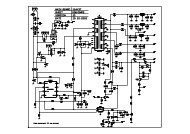
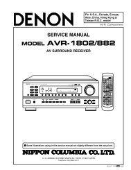
1234532SDRAM61524306152430524312345678910SCHEMATIC DIAGRAMSMAIN PCB (1/3)VCC1.2VCC1.8VCC3.3DL400AG7001005VCC3.3AL401AG7001005GNDC423B0.1u0603C412B0.1u0603C403B0.1u0603C404B0.1u0603C408B0.1u0603C409B0.1u0603C411C405B1u1005C401B1u1005C428B0.1u0603C424C402B1u1005C420B0.1u0603C415B0.1u0603B0.1u0603C427B0.1u0603C414B0.1u0603B0.1u0603VCC1.2VCC1.8VCC3.3DVCC3.3ASD_DETP80015 VSSGNDWRITE_PROTECTP801SDWP14 SDWP13 VSSSDCD12 SDCD11 SDDAT210 SDDAT1SDDAT2SDDAT1SDDAT09 SDDAT08 VSSSDCLK7 SDCLK6 VDDB0.1uC8005 VDD4 VSS3 VSS2 SDCMD1 SDDAT306030603R805 47k0603R803 47k0603R802 47k0603R801 47kHW680 1005 L807HW680 1005 L808HW680 1005 L806HW6801005L800HW680 1005 L805HW680 1005 L804SD-BUSSDCMDSDDAT3SD-CONNECTERSCDA3A0600CN8000603R804 47k0603R800 10kUNFIXC8011608VCC3.3DBD102L8011005STROBE-BUSIGBTCNTCHG22kR820CENDN0603VCC5-2VCC1-0to_Strobe_CNGND10 VCC1-09 VCC1-08 NC7 GND6 GND5 NC4 PWRCNT3 I GBTCNT2 VCC5-21 READY51441-1093CN803VCC1-106030603 D220kD220kR482R4831608R481C468D220k06032.2uFGND10VPWCTL5MOTOR-BUSCCD-BUSPWCTL-BUS8BIT-BUS 8BIT-BUS 8BIT-BUS 8BIT-BUSCRADLE-BUSCRADLE-BUSPWCTL-BUSMOTOR-BUSMOTOR-BUSMOTOR-BUS8BIT-BUS8BIT-BUSKEY-BUSKEY-BUS8BIT-BUSKEY-BUSKEY-BUSSHUT_CLOSE_TRGSHUT_CLOSE_TRGDRAM_RESETDRAM_RESETCRADLE-BUSCRADLE-BUSLCD-BUSLCD-BUSLCD-BUS8BIT-BUS8BIT-BUS8BIT-BUS8BIT-BUSAUDIO-BUSAUDIO-BUSAUDIO-BUSMOTOR-BUSMOTOR-BUSMOTOR-BUSPSRSTBPSCKPSRDYPSOUTPSINMT_SCKCDTIMT_DATACCLKBLPWMMT_STBAFLED_CSELFLEDR-LEDDRAM_RESETG-LEDUSB-LEDWATCHMCKOCSNLRCKBICK0603R400VBUS 390AVR-M1005C120MTAABD400GNDZ_ENC_DETL810ACM1210-900-2PT000DMINUS14DPLUS 2 3FOCUS2FOCUS1FOCUS0IRIS2IRIS1ZOOM0SDTOSDTIIRIS0VCC3.3DVCC1.8VCC1.2VCC3.3DVCC1.8VCC1.2VCC3.3DVCC1.8VCC1.2VCC3.3DVCC1.8VCC1.2SDCLKSHUT_CLOSE_TRGD-1.2VSDRAM I/OVCC3.3AVCC3.3DVCC1.8VCC1.2301302303304305300299SDCMD298306P137/RXD2307P135/SCLK1308 P136/TXD2309 P132/SCLK0310P133/TXD1311P140/SCLK2312 P17/TB07313P130/TXD0314P134/RXD1315VCCX1_8316P14/TB04317P15/TB05318 P131/RXD0319VCC_7320VSSX_22321 P12/TB02322 P11/TB01323P16/TB06324VSS_8325VDDQ_7326DSE#327 P10/TB00328P13/TB03329VCCX1_9330 VSS_SD_15331 MRES332SAMRES333P77334VSS_90603 3354.7k VDDQ_8336 R/B#R402338P75339FVCC_2340 VSSQ_9341P45/MCLKOUT1342 RS#343P44/MCLKOUT0344FVSS_3SDRAM I/O 345 VDDQ_9346CS0#347 SACE#348P74349VCC_8350 VSS_SD_16351 P40/LRCLK352P73353P41/BICK354 VSS_SD_17355VCC_9356VBUS357 DV33358P72359VDD_17360VSS_10361 DG33VCC1.2A 362AV12363P71364VCCX1_10365VCC_10366DM367AG12368 P70369 P116/MTDCPLS3370VPP371DP372 DG12373P111/MTFB0374P115/MTZB0375 VDD_18376 AG33377DV12378P106/MTFA1379 P114/MTZB1380VSSQ_10381REFRINR403 382AV33F5.6k 383 P107/MTFA00603 384P110/MTFB1385VDDQ_10386 WP#387 P102/MTIB1388P103/MTIB0389P112/MTZA1390VSS_SD_18391P105/MTIC0392P104/MTIC1393P100/MTIA1394 P113/MTZA0395P42/STDI396P43/STDO397VA_STBYSHUTTER2SDDAT0SDDAT1SDDAT2SDDAT3SDWPSDCDOFDC1KINTBSHUT_CLOSE_TRGFOUTSHUT_CLOSE_TRGIGBTCNTAVDETCDLOADCDRST297A17296A5/MA3295VDD_166 294P24/TB14VSSX_207 293P05/INT5A188 292P20/TB10A4/MA29 291P27/TB17A3/MA110 290AUDAT3VSS_SD_1411 289X27OUTVCCX1_712 288VSSX_2P52/SD0DAT013 287AUDAT2A2/MA014 286AUDAT1A12/MA1015 285VDD_1VDD_1516 284X27INVSSX_1917 283TDIP53/SD0DAT118 282AUDAT0A15/BA119 281VCCX2_1A16/BA020 280VSS_SD_1VSSX_1821 279TMSVCCX1_6R404 22 278TRST#P54/SD0DAT223 277100k 0603 TDODCS1#24 276VSS_1SDCS1#25 275VDD_2VCCX1_526 274XOUTVSSX_1727 273TCKP55/SD0DAT328 272AUDSYNC#DCS0#29 271VCCX1_1SDCS0#30 270VSSQ_1VSS_SD_1331 269XINVCCX1_432 268VSSX_3P56/SD0WP33 267AUDCLKP57/SD0CD34 266ASEBRKAK#RAS#35 265VDDQ_1VDD_14R405 36 264ASEMD0#VSSX_1637 2634.7k 0603 P03/INT3P151/CDOFDC38 262P04/INT4P152/CDSHUT39 261VCCX1_2CAS#40 260VSSQ_2VSS_SD_1241 259RTCCLKINVCCX4_242 258P01/INT1P153/CDSHUTM43 257P02/INT2P154/STLGTSIG044 256VSS_2DWE#45 255VDDQ_2SDRAM VDD_13R406 46 254P00/INT0VSSX_1547 253100k 0603 DQM0/WS0#P155/STLGTSIG148 252WKUP#P60/SD1CMD49 251VCC_1P61/SD1CLK50 250VSS_SD_2VSS_SD_1151 249SYSCLKVCCX4_152 248DQM1/WS1# P63/SD1DAT153 247STBY#P62/SD1DAT054 246VSSX_4DCKE55 245VDD_3VDD_1256 244DQM3/WS3#VSSX_1457 243DQM2/WS2#/A1P64/SD1DAT258 242P156A11/MA959 241VCCX2_2A13/MA1160 240VSS_SD_3VSSQ_861 239D15VCC_662 238D0P65/SD1DAT363 237P127A9/MA764 236VSSX_5 A10/MA865 235VDD_4VDD_1166 234D1VSS_767 233D2P66/SD1WP68 232P97A7/MA569 231VCCX2_3A8/MA670 230VSSQ_3VSSQ_771 2290603 D13VCCX5_2B0.1u 72 228D14P67/SD1CDC432 73 227RST#A14/MA1274 226VSSX_6A6/MA4SDRAM I/O 75 225VDDQ_3VDD_1076 224D12VSSX_1377 223D3P80/CDPLS078 222MODE2P81/CDPLS179 221VCCX2_4P82/CDPLS280 220VSSQ_4VSS_SD_1081 219D11VCCX5_182 218D4P83/CDPLS383 217MODE1P84/CDPLS484 216VSSX_7P85/CDPLS585 215VDD_6VCC_586 214D5P90/CDPLS887 213D6P87/CDPLS788 212MODE0P86/CDPLS689 211VCCX2_5CDDAT6D 1.8V 90 210VSS_SD_5CDDAT791 209D9CDDAT1092 208D10CDDAT393 207TESTCDDAT494 206VSSX_8CDADCLKD 1.8V 95 205VCCX2_6VSSX_1296 204D8AVSS_297 203D798202P50/SD0CMDP51/SD0CLKP33/PSRSTP32/PSCKP34/PSRDYP31/PSINP30/PSOUTVSSX_21337 165P76 20 316 317 318 319 320VDDQ_6190 189 188 187 186 20164VSS_516319 321 322 323 324 325185 184 183 182 181 19P143/SCLK3162AN1016118 326 327 328 329 330180 179 178 177 176 18AVREF0160VSS_SD_815917 331 332 333 334 33517VCCX3_2175 174 173 172 171158LDDAT715716 336 337 338 339 340170 169 168 167 166 16AN11156AN1215515 341 342 343 344 345165 164 163 162 161 15SDRAM VDD_8154IC400VSS_415314 346 347 348 349 350160 159 158 157 156 14LDDAT6152AN1315113 351 352 353 354 355155 154 153 152 151 13AVREF1150VSS_SD_7R8J30214AEBGV14912 356 357 358 359 360VCCX3_1150 149 148 147 146 12148LDDAT414711 361 362 363 364 365LDDAT5145 144 143 142 141 111463983994004018BIT-BUSP101/MTIA0P26/TB16P25/TB15P23/TB13DUMMYVSSX_1P07/INT7P22/TB12P06/INT6P21/TB11VCC1.2VCC1.8VCC3.3DJTAGRESET R412 PADP400TDIVCCX1P401TMSP402TRSTP403TDOP404TCK2524232221R40939006031 4C430CH8p0603306307309312X40048M3083C300301 297 292 287 282 277 272 267 262 257 252 247 242 237 232 227 222 217 213 210 208 204 203302 298 293 288 283 278 273 268 263 258 253 248 243 238 233 228 223 218 214 211 202 201 200311 299 294 289 284 279 274 269 264 259 254 249 244 239 234 229 224 219 215 199 198 197 196314 315 295 290 285 280 275 270 265 260 255 250 245 240 235 230 225 220 195 194 193 192 1915ASEBRKAKP405790603C431CH8pASEMD0E B G H J K L M F291P40622276 271WKUPB26110 366 367 368 369 370140 139 138 137 136 109 371 372 373 374 375135 134 133 132 131 98 376 377 378 379 380130 129 128 127 126 87 381 382 383 384 385125 124 123 122 121 76 386 387 388 389 390 401120 119 118 117 116 65 391 392 393 394 15 20 25 30 35 40 45 50 55 60 65 70 75 80 85 90 95 115 114 113 112 54 395 396 397 10 14 19 24 29 34 39 44 49 54 59 64 69 74 79 84 89 94 99 111 110 109 432A305 3033984001 1AVCCX13043103133992B46CHWED2968D131211E2861817F2812316 21G28H332664327 32 37 4252STBYB24624163236686726 31 36 41 46 51 56 61 66J38KL25648251231(top VIEW)VCCX447MVCC1.2VCC1.8VCC3.3DN53N8BIT-BUSPDNR41200603RESETBOFDC2CHGCENDNZ_HOME_LEDF_HOME_LEDCDDAT6CDDAT7CDDAT10CDDAT3CDDAT4ADCLKAVGAP144/CDDAT1AVCC_2AVGBCDDAT5CDDAT2DACK#CS1#D16RSTOUT#READY#CDDAT11005C4226.3V1uF201AVSS_1CDDAT9P145/CDDAT0AVCC_1AVOUTBVSS_SD_9CDDAT8P37/ATGPLS0P36/ADTRG1CDDAT11P147/CDHDP35/ADTRG0P146/CD<strong>EX</strong>TCLK0603AUDIO-BUSAUDIO-BUSCRADLE-BUS CRADLE-BUS CRADLE-BUSLCD-BUSLCD-BUSLCD-BUSDRAM_RESETDRAM_RESETSHUT_CLOSE_TRGR4101MP5857PVCC3.3AVCC3.3DVCC1.8VCC1.2R62RTTU737271UV226787776VCCD-BUSW221838281WY216888786YAA212939291AAVCCX5AB209989796ABAC207102101100ACAD206108104103ADAE205107106105AE2524232221132VCCX5VCC3.3DD-1.2VCCD-BUSVCC1.8SDRAMP150/CDVDFVCC_1VSSX_11P141/TXD3FVSS_2P142/RXD3VDDQ_5FVSS_1LDDAT3P126/LDSCLKVSSQ_6P121/LDDAT0P120/LDDAT1LDDAT2P124/LDCSP123/LDVDP122/LDHDVSSQ_5VCCX2_8P125/LDSTOVDDQ_4VSSX_10VSS_SD_6VCCX2_7VBB_CNTRLVCCX1_3VSSX_999DRAM_RESETAVOUTVDD_9AIREFVCC_4AVRVSS_6AN01AN00AN02AN03VCC_3AN05AN04PRELDCLKVCC_2VDD_7VSS_3D23D31VBGPD22D30D21D29VBGND20D28DREQ#100D19D27D18D26D25D17D24VCC3.3AVCC3.3DVCC1.8VCC1.2200199198197196195194193192191190189188187186185184183182181180179178177176175174173172171170169168167166145144143142141140139138137136135134133132131130129128127126125124123122121120119118117116115114113112111110109108107106105104103102101B1u 1005C421F220R4080603F3.3kR4070603B1uC4191005D-1.2VVCCX3VCCX3SDRAM I/OD-1.2VVCC1.2VCC1.8VCC1.2VCC1.2VCC1.2VCC1.8VCC1.8VCC1.8VCC3.3DVCC3.3AVCC3.3DVCC3.3DVCC3.3DVCC3.3ACDDAT5CDDAT2CDDAT9CDDAT0CDDAT8CDDAT11CDHDCDVDCDSDTCDSCSCDSCKF_HOME_DETLDDAT7Z_HOME_DETLENS_THLDDAT6LDDAT4LDDAT5LDDAT3LCDCLKLCDSCKLDDAT2LCDCSVSYNCHSYNCLCDDICCD-BUSMOTOR-BUSVIDEOCCD-BUSLCD-BUSLCD-BUSMOTOR-BUSCRADLE-BUS CRADLE-BUSCRADLE-BUS8BIT-BUSCRADLE-BUSCRADLE-BUSCRADLE-BUSVCC15P110BLLEDABLLEDKP111CRADLE-BUSQ109R124D1001005GNDR125D5.1k0603USB-LEDLCD-BUSVCC3.3AR1220603R126D1.31k0603EMX2T2ROn SemiconductorNSBC123JPDXVQ802CRADLE-BUSGND2KEY-BUSR600681005R60101005EVCC3.3PSRSTBKIN4KIN2R123100k0603RESETBFOUTC600B1u25V16083 Q108SSM3J16TEGNDC466C464C457C454BLPWMLDDAT2LDDAT4LDDAT6VCC5-11005VCC3.3A C442 B1uGLF1608T220M100522u 1608 1 CP2L440 CP110 B1u2V+2V- 9 C4433VIDEO C440GND21608 V+18C441 4B1u 75VINGND1 71005B4.7u 5R440VA_STBYVOUT 6POWER_SAVE0603R441IC4400NJW1331KK1(TE3)0603GND VGND VGND8BIT-BUS1C601B1u6.3V1005BLPWML:BrightH:NormalBATTEMP10051uF1uF1uF6.3V6.3VF160kR4530603LCDCLKVSYNCLCDDIR456F75kKIN44.7kR812EVCC3.3F22kR813100506036.3V06031005B0.1uCHGCTLVOUT0603F56kR45406030603R455F160kC6024.7uF10V10V 1608C6032.2uF0603EVCC3.3EVCC3.32012AVDETDMINUSDPLUSEVCC3.3R451C450R452C451L803AG700BLM15AG700SN1DC8020603B0.01uL802AG700BLM15AG700SN1D100k0603B0.01u0603B0.1u06030603C452 B0.01uC453 B0.01u06030603C456 B0.01uC455 B0.01u0603C458 B0.1u060333 VSS31 COMOUT29 C1-27 C2-25 VDC123 VDD21 VSH19 NC17 D0015 D0213 D0411 CLK9 VSYNC7 DI060310kR457 100k0603C469 B0.1u0603R458 00603C459 B0.1u0603R60310k 06035 BLON3 STSTM1 VCOMC1+VGLC2+VBCD01D03D05SCKCSVSSCN600 FL2S033JA1R3000JAPAN AVIATION ELectronics.IND.to_LCDGND15 NC11 NCVVCOMVGHCOMDCNCCN802HSYNCPOCB14 AVDET12 AGNDR41-8931AEVCC3.3R4591MX45032.768kFC135-32.7-9/20C60825V1608 1uF3230282624222018161412102.2intch 3G 6bitLCD:COD22T25198 (354H 240V)22pinLCD-BUSCRADLE-BUS8642GND1GND113 MONOOUTGND1GND1DC72711 NC_12IC13 SUB_OUT1to_CLADLEPAD(P107)EVCC3.3IC270P41CH8pC460C60710V 2.2uF060310 CHGCTL DC 219 CRDLSW CHARGE 228 BATTEMP CHARGE 237 USBLED CHARGE 246 VOUT CHARGE 255 USBGND USBVCC 264 USBGND USBGND 273 D- USBGND 282 D+ USBGND 291 USBGND USBGND 30PWCTL3PWCTL0VBUSSHUTTER20603 POWSWC462B0.1u0603LDDAT3LDDAT5LDDAT7HSYNCLCDSCKLCDCSKIN2KINTBR480100k 06030603 100k R4780603 100k R4790603B0.1u C467100k R4770603C605 CH100pDCPSRDYC463B0.1u0603KIN1KIN4KIN3THMONOOUTC465B0.01u0603AFLED_CSELFLEDR-LEDG-LEDPSCKSTBYBPSINPSOUTPWCTL5PWCTL4WKUPBCHGCTLPWCTL1HALFSHUTADPINBATTEMPPWCTL2WATCHSHUTSWAFLEDK1608D600RB521S302 1VCC5-2C6062012 B4.7u25V0603694 SUB_XT11617181920P43685 SCL_RTC0603P140/PCL/INTP6676 SDA_RTCP141/BUZ/INTP70603667 SUB_XT2R4600603P14/RXD6658 VDD_SUB0603P04649 VDD_RTCC461OPENR602 560kP00/TI0006310REQ_RTCGNDP01/TI010/TO0062P30/INTP1R4761k61P21/ANI16011 EVSS12VSS13 REGC14 P124/XT2R473100k 060315 VDD16 EVDD17 P6318 P123/XT1CHGVCC19 P61/SDA0R474100k 0603R4750603 D10k73 VSS_RTC48AVSS74P120/INTP047P4275 46COMP_OUT1 P10/SCK10/TXD076 45COMP_OUT2P13/TXD677IC450P11/SI10/RXD0 44VLC_RTC78 P12/SO10 43IC8bit-MICON P16/TOH1/INTP579UPD78F8011F1AQ1E2A42PORT_INP17/TI50/TO5080 41PORT_OUT 8 84 82 79 75 71 67 63 59 55 52 50 49 P15/TOH081 40AGNDP5382 39COMP_REF27 85 83 80 76 72 68 64 60 56 53 51 48P5283 38COMP_IN1 6 86 87 81 77 73 69 65 61 57 54 47 46 P5084 37NC_5NC_385 36AVDD5 88 89 90 78 74 70 66 62 58 45 44 43NC_286 35COMP_IN2 4 91 92 93 10 14 18 22 26 30 42 41 40 P0587 34COMP_REF1P70/KR088 33RESET3 94 95 6 9 13 17 21 25 29 33 39 38P32/INTP389 32P402 96 3 5 8 12 16 20 24 28 32 35 37 P71/KR190 31P122/X2P73/KR391 30P121/X11 1 2 4 7 11 15 19 23 27 31 34 36P5192 29VDD_MAINA B C D E F G H J K L MP0693 @referP31/INTP228/VDD_MAINTop View94P33/TI51/TO50/INTP4P74/KR427VDD_LVIP60/SCL0 P75/KR595 26SUB_OUT296 25REGC_RTCP72/KR21005GNDC604B1u6.3VC4066.3V B1u1005P0359P0258D450HSD226P24/ANI457P27/ANI756P20/ANI055P13054AVREF53P23/ANI35220 P6221 P76/KR6P22/ANI25122P26/ANI65023P25/ANI54924R4626.8k0603R4616.8k0603R4632701005C480PAS414HR-VE5RshoeiGNDKEY-BUSEVCC3.3C700 B1uNC_4P77/KR73Q4502SC58460021005EVCC3.3Knowles&SP0103NC3-334IC701GNDOUTPUT1POWERMICKEY-BUSGAIN 2C702B0.1u100k 0603R469100k 0603R468R70012k100k06030603100k0603100kR48447k06031GND20kR70406030603GNDP700G-shortP701G-shortR472R465R464AGND0603R7133.3k0603R466F16kR467F3.6k06030603Q801EMH25T2R1 6220R7020603EVCC3.3R8102700603GNDC717B0.022u6.3V 06038BIT-BUSVCC3.3AAGNDPWCTL-BUSPWCTL-BUSVBUSB1uC7031005GNDR80620R80739KEY-BUSKEY-BUSGNDR823R822R821VCC5-20603060306030R7070603F22kF22kF22kKIN3KIN2KIN1HALFSHUTR471 0603 1kSHUTSWR470 0603 1k0603NCNC_8 30VCOMMIN 29 6.3V B10uC7096.3V B10uB0.1u AVDDSVDD 28 C71320120603C712AVSSSVSS 27NC_1NC_7 26 20120603VCOCSPN 25C714 R708B4700p10kCSNMCKO 240603PDNSPP 23CCLKMCKI 22NC_2NC_6 21311005 NC_932 AK4631VGAOUT33 7 31 29 27 25 23 22 21C704 BEEPB1u 34 6 32 30 28 26 24 20 19MOUT35 5 33 3418 17AIN36 4 35 36 IC700 16 15B1u 1005 NC_1037 3 37 38 41 14 13C701 MICOUT38 2 39 40 4 6 8 10 12NC_1139 1 1 2 3 5 7 9 11MPIB1u 1005 40A B C D E F GMICC706 41NC_12C7106.3V B2.2u1608C711B0.1u10051608R7064.71005CRADLE-BUSCRADLE-BUSKEY-BUSKEY-BUSPOWSW2 1VDZ 5.1BD700SPPSPN2 120DVDD19DVSS18BICK17NC_516FCK15NC_414SDTI13SDTO12CDTI11NC_3C470B0.1u 1005C471B0.1u 1005EVCC3.3VDZ 5.1BD701GNDGNDR7093300603GND0603B0.1uC716R711GND0603B0.1uC803C804B0.1u06030603B0.1uC805R710 100k0603100k0603R7121010051 POWSW2 GND3 SHUTSW4 HALFSHUT5 EVCC3.36 KIN17 KIN28 AFLEDA9 AFLEDK10 GND11 RLED12 GLED13 SP+14 SP-15 KIN316 EVCC3.317 NCCN801CFP7517-0250FSMKMCKOBICKLRCKSDTISDTOCDTICCLKPDNCSNAUDIO-BUSto_KEY-FPCAUDIO-BUSAUDIO-BUSAUDIO-BUSGNDKEY-BUS KEY-BUS KEY-BUS KEY-BUS— 27 —
— 29 —MAIN PCB (3/3)PWCTL0PWCTL3PWCTL2PWCTL1PWCTL4THPWCTL1PWCTL5ADPINVCC1-1Q103SI5513DC1237684 5VCC15VCC1.2GNDC102 B10u20126.3VGNDD102RB551V-3012GNDIC1021.2VXC9215A12CDR1LX 2VSS1 3VOUT4CE/MODE5 VSS26 VINC121B1u10056.3VGNDVEE7.5D101RB551V-301 2VCC5-2C103 B10u2012 6.3VR11811005VCC5-1C110B22u20126.3VVCC1-2D100CUS0112C104 B10u 2012GRM21BB10J106ME01LC109B10u20126.3VVCC1-1Q104SI1013R123C126B10u201210VL1014.7uP108THDCGNDGNDEVCC3.3VCC1-1P107BAT+P109BAT-C10610V47uF951A476MAAAQ2C10510V47uF951A476MAAAQ2C120B10u20126.3VR110D56k0603R114D2k0603R113D2k0603VCC1.8GNDIC1031.8VR1115Z181D-TR-FDVDD1CE2GND3VOUT4VCC1-1EVCC3.3GNDVCC3.3DGNDC113B10u20126.3VVCC5-1VCC3.3AC119B0.33u10056.3VC122B0.33u10056.3VC124CH56p060325VR11711005IC1053.3VR1115Z331D-TR-FDVDD1CE2GND3VOUT4GNDC108B0.022u06036.3VCHGVCCGNDVCC1-0VCC1-2L1058.2uCDRH2D14NP-8R2NC-TR11922k0603R100100k0603R1021M 0603R10747k0603R106F15k0603R10910k0603R111F75k0603R115470k0603R1161M0603R10800603R11200603R10400603R10500603R13000603R13100603R13200603R13300603R13400603P100P130C123CH5p0603IC1103.3VXC6219B332MRVIN1VSS2NC4CE3VOUT5C12525V B4.7u 2012C12725V B4.7u 2012L1006.8uNR4018T6R8MFU1002.5AERBSD2R50UGNDIC1003.3VVSS1VIN2VOUT3NC4IC107R1280Z002B-TR-FDVFB1 1CE 2GND 3<strong>EX</strong>T1 4<strong>EX</strong>T26VIN7VREFOUT8VFB29DTC2 5DTC110DUMMY11Q100&NTJS3157NT1G123546Q102NTJS3151PT1G123546Q107NTJS3151PT1G123546IC1015.0VXC6367A505DR<strong>EX</strong>T1VDD2CE4GND3NC5FB6C100B1u10056.3VC101B1u10056.3VC111B1u10056.3VC112B1u10056.3VC115B1u10056.3VC116B1u10056.3VL104CDRH2D14NP-6R8Q101DTC144EM3T5G213Q105DTC144EM3T5G213FU1010.75AERBSD0R75UC114B1u160825VR120100603R1211k0603Q106DTC123EMT2L213D103CUS02(TE85L.Q)12VCC15CDRH2D14VEE7.5POWER-BUSVCC1.2VCC5-1VCC1.8VCC5-2PADEVCC3.3SATURNLENSSDSATURN(ANALOGUE)AUDIOVIDEOLCDSPEAKERMOTORSTROBEto 3.3V
Ver.1 : July. 2005• Correction of the DISASSEMBLY (P19)Ver.2 : Aug. 2005• Correction of the THE TEST MODE (P6)• Correction of the THE COUNTERMEASURE FOR "SYSTEM ERROR" (P17)Ver.3 : Sep. 2005• Correction of the <strong>EX</strong>PLODED VIEW (P22)• Replacement of the PARTS LIST (P23, 24)Ver.4 : Nov. 2005• Correction of the THE TEST MODE (P6)Ver.5 : Dec. 2005• The program for <strong>EX</strong>-<strong>S500</strong> has been changed. (P6 ~ P9)CASIO COMPUTER CO.,LTD.Overseas <strong>Service</strong> Division6-2, Hon-machi 1-ChomeShibuya-ku, Tokyo 151-8543, Japan