Keywords: Differential Scanning Calorimetry, DSC, Heat Flow, Phase Transitions, Crystallinity, Degree of Cure
TA039
Introduction
The purpose of this paper is to assist DSC users with interpretation of unusual or unexpected transitions in DSC results. The transitions discussed in the paper are several of the ones that most frequently create problems for the new user, and which can also fool even an experienced thermal analyst.
By applying some of the recommended procedures and solutions, most laboratories will be able to improve the overall quality and interpretation of DSC results.
Background
Differential scanning calorimetry (DSC) is a thermal analysis technique which measures the temperature and heat flow associated with transitions in materials as a function of temperature and time. Such measurements provide quantitative and qualitative information about physical and chemical changes that include endothermic/exothermic processes or changes in heat capacity. Specific information that can be obtained include:
- Glass transition temperatures
- Melting points & boiling points
- Crystallization time & temperature
- Percent crystallinity
- Heats of fusion and reaction
- Specific heat
- Oxidative stability
- Rate of cure
- Degree of cure
- Reaction kinetics
- Purity
- Thermal stability
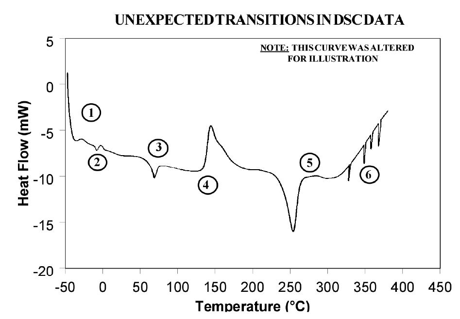
Because of the wealth of information provided and because DSC is easy-to-use, DSC has become the most commonly used thermal analysis technique. Ease-of-use in this case refers to sample preparation and experimental setup, as well as interpretation of the results. There are, however, some common DSC events/transitions that can be the cause of less than optimum results and/or misinterpretation. This paper describes several of these events with causes and solutions. Figure 1 is an artificial DSC curve which was generated to illustrate these events/transitions. The curve is artificial in the sense that all of these events would not occur in the same real world DSC curve.
Interpretation of Events and Transitions
Event 1: Large Endothermic Start-up Hook
Causes
At the beginning of a programmed heating experiment, there may be significant baseline change (usually endothermic) which occurs primarily based on differences in the heat capacity of the sample and reference. Since heat capacity is directly related to weight, an endothermic shift indicates that the reference pan is too light to offset the sample weight. This effect is heightened by faster heating rates.
When operating subambient, the thermocouple junctions in the DSC cell base may get cold as cold is transferred from the cell cooling head. This effect increases as the temperature is lowered and/or the time at lower temperatures is increased.
Effects on Results
A large “start-up hook” or a sloping baseline make detection of weak transitions difficult. In addition, during the first 2-3 minutes of the experiment, transition temperatures and measured heat flow (DH) may not be reproducible.
Solutions
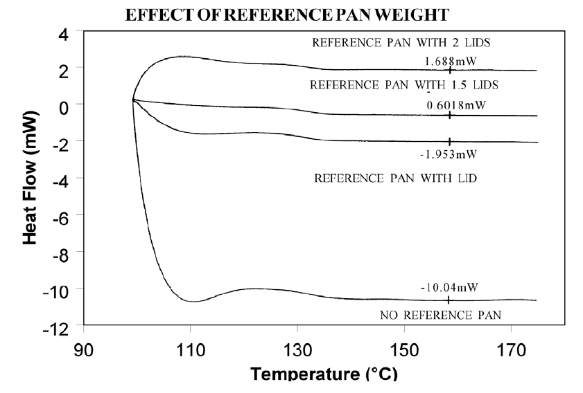
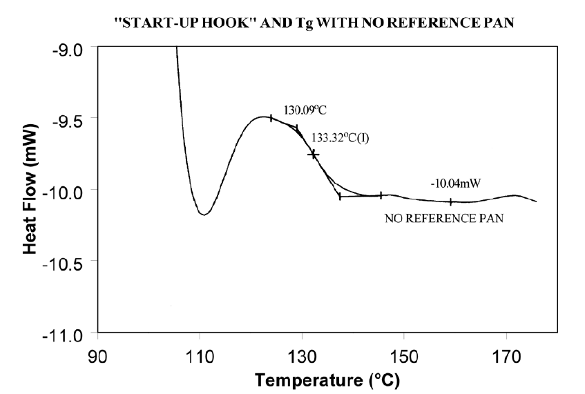
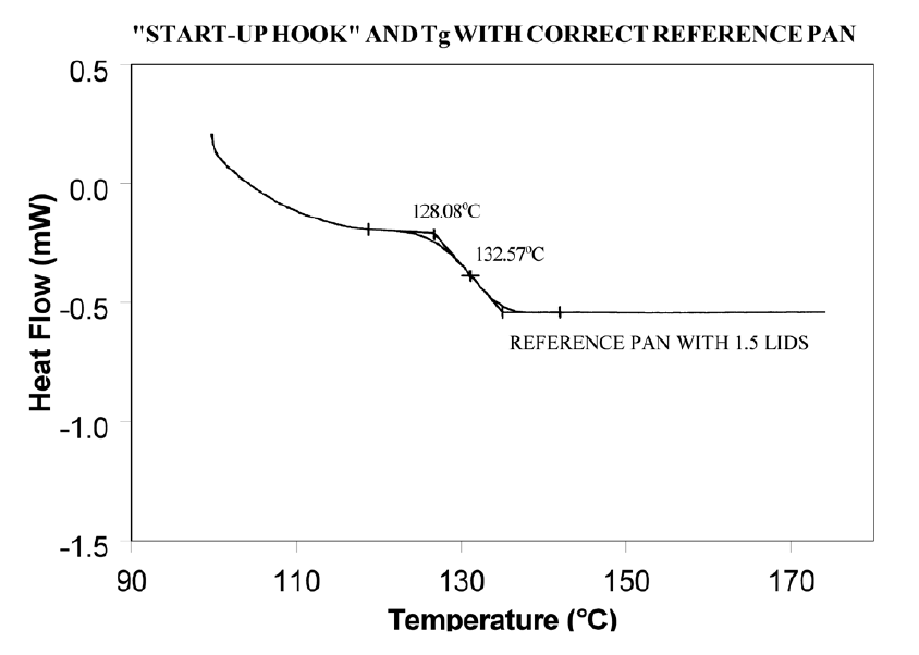
Using aluminum foil or additional pan lids, make up a series of reference pans of different weight (2 mg. increments). When running a sample use a reference pan that weighs 0–10% more than sample pan. Figure 2 shows results with an epoxy prepreg sample. Best results are achieved with 1.5 lids. 2 lids results in overcompensation and an exothermic start-up hook. Figures 3 and 4 show how the glass transition results are affected by correct compensation. Note: these results are obtained heating at 20°C/minute from a 100°C isothermal hold. The impact of the start-up hook can also be reduced by initiating the heating at a temperature that is at least 2-3 minutes below the range of interest at the heating rate chosen (ie. at 20°C/minute, start experiment at least 50°C below the first thermal event of interest.)
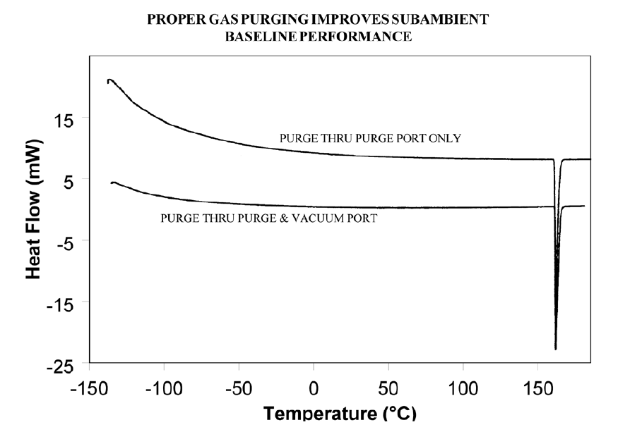
If operating below 0°C, use 50cc/minute dry nitrogen purge gas through the cell base VACUUM PORT plus the normal purge gas. Figure 5 illustrates the typical improvement obtainable.
Event 2: Transition(s) at 0°C
Causes
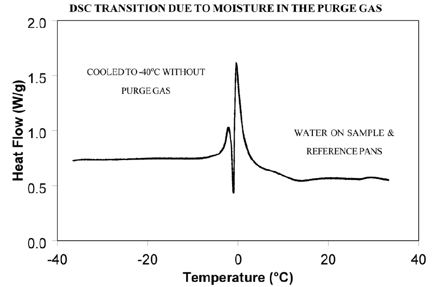
Weak transitions around 0°C indicate the presence of water in the sample or the purge gas. These transitions are usually endotherms, but may appear different than a melting peak. Since water can condense on both the sample and reference pans, the transition often appears as shown in Figure 6. Furthermore, the peaks may appear slightly lower than 0°C due to impurities dissolved by the moisture from the cell and pans.
Effects on Results
If water is in the sample, results may not be reproducible because it can act as a plasticizer and reduce transition temperatures. The water will also volatilize during the run, causing an endothermic peak and a shift in the baseline.
If water is in the purge gas, it causes a perturbation in the baseline that makes it difficult to detect real transitions near 0°C.
Solutions
Keep hygroscopic samples in a dessicator and load them into pans in a dry box.
Weigh the complete sample pan (with sample) before and after the run. A change in weight could explain an unexpected transition.
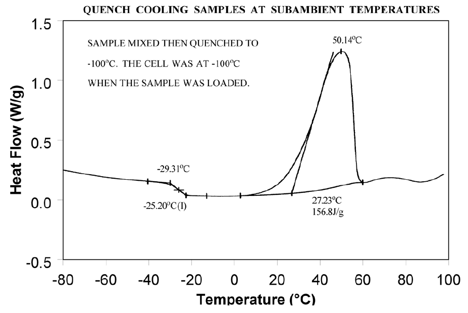
Dry the purge gas by placing a drying tube in the line. Figure 7 shows an epoxy sample after loading at -100°C. The absence of any transitions at 0°C indicates that with proper precautions water condensation in the cell can be eliminated even under conditions which favor condensation. Note: Loading a sample at temperature below 0°C is only possible when using the liquid nitrogen cooling accessory (LNCA). Samples should always be loaded above 0°C with any other cooling accessory.
Event 3: Apparent “Melting” at Glass Transition (Tg)
Causes
Stresses built into the material as a result of processing, handling or thermal history are released when the material is heated through its glass transition. The reason this occurs at Tg is that the molecule goes from a rigid to a flexible structure and thus can move to relieve the stress.
Effects on Results
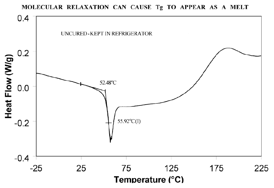
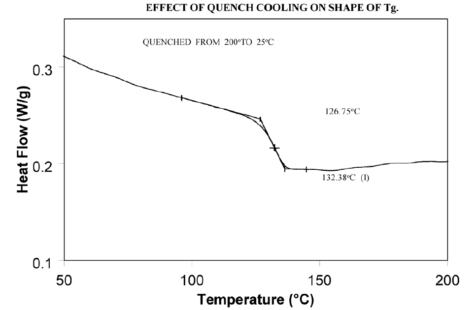
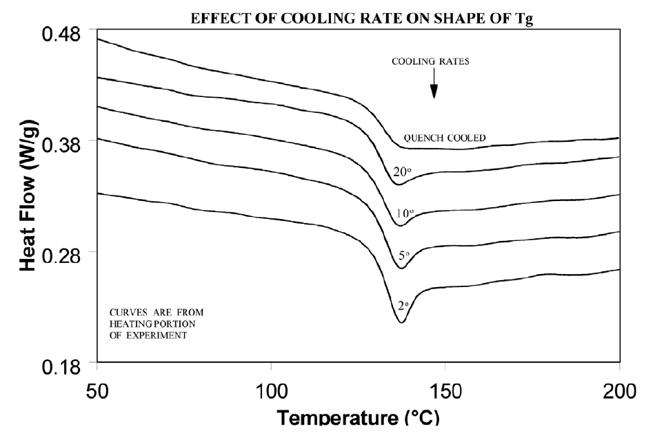
Molecular relaxation usually appears as a weak endothermic transition near the end of a glass transition. As shown in Figure 8, this behavior can be pronounced enough to either shift the measured glass transition temperature several degrees or lead to misinterpretation of the Tg as an endothermic melting peak.
Solutions
Relieve the internal stresses in the material by heating it to at least 25°C above the Tg and then quench cooling it to a temperature below the Tg. Figure 9 shows the same material as in Figure 8 after curing at 200°C and then quench cooling to 25°C.
Event 4: Exothermic Peaks Below Decomposition Temperature While Heating
Cause
Exothermic behavior results during curing of a thermosetting resin or crystallization of a thermoplastic polymer. The amount of heat associated with these transitions can be used to determine degree of cure and % crystallinity respectively provided scans of suitable standards are available.
When an exotherm is obtained in a polymer’s DSC profile at a temperature which the operator suspects is too low to be a decomposition, running the material in the TGA aids evaluation. The absence of a TGA weight loss which coincides with the DSC exotherm indicates that the exotherm is crystallization or curing.
Effects on Results
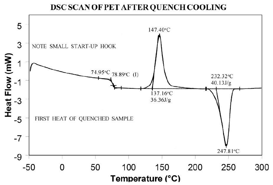
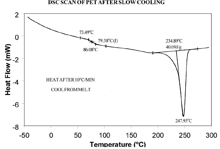
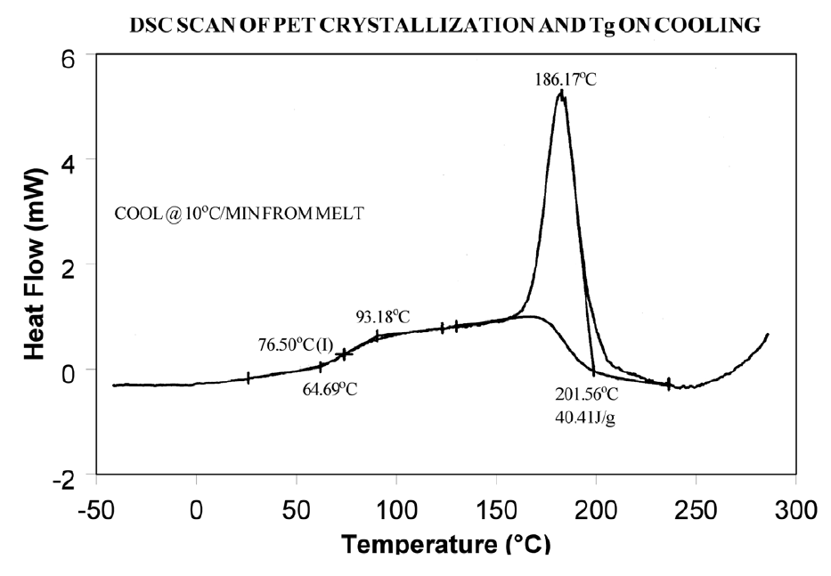
The presence or absence of exothermic crystallization peaks in thermoplastic materials is very dependent on thermal history. Therefore, DSC results will not be reproducible if thermal history of the sample is not tightly controlled. Figures 11 and 12 illustrate the different results obtained for PET after quench cooling and programmed cooling at 10°C/minute respectively. The quenched material has a well-defined Tg indicating significant amorphous structure which rearranges on heating to a crystalline structure before melting at about 235°C. The DH of crystallization is slightly less than the DH of melting which indicates that the initial structure is mostly amorphous. The slowly cooled material has a weak Tg, indicating an initial structure that is almost entirely crystalline. Since it is crystalline at the start of the DSC experiment, no additional crystallization occurs prior to the melt at 235°C.
Solutions
When comparing thermoplastic materials, give the materials a common known thermal history by either quench cooling or program cooling from above the melting temperature. ASTM D3418-82 defines recommended procedures for giving polymers a known thermal history.
Event 5: Baseline Shift After Endothermic or Exothermic Peaks
Causes
Baseline shifts are caused by changes in sample weight, heating rate, or the specific heat of the sample. A change in specific heat often occurs after the sample has gone through a transition such as curing, crystallization, or melting. Sample weight often changes during volatilization or decomposition.
Effects on Results
Since ΔH is calculated on the basis of sample weight (J/g, BTU/lb, etc.), any calculation of DH after a weight change will be in error. Integration of a peak which has a baseline shift is difficult and typically less accurate because of operator subjectivity in setting integration limits and baseline type.
Solutions
Weigh the sample before and after a run to determine if weight loss has occurred.
If crystallization or melting is the cause of the transition, compare the DH of the transitions, using different limits and types of baselines. Figure 13 illustrates an example where use of sigmoidal baseline is required.
Event 6: Sharp Endothermic Peaks During Exothermic Reactions
Causes
Sharp peaks similar to those in Figure 1 above 300°C, are usually the result of experimental phenomena rather than real material transitions. For example, rapid volatilization of gases trapped in the material can cause sharp peaks, as can rapid volatilization of gases trapped in a partially sealed hermetic pan.
Effects on Results
Erroneous interpretation of these sharp endotherms as melting peaks associated with minor components is possible.
Volatilization can be detrimental to obtaining accurate quantitative results since sample mass changes. If the volatiles are corrosive, such as halogenated flame retardants, DSC cell damage can occur with extended operation.
Solutions
Weigh the sample before and after the run to determine if weight loss has occurred.
Reduce the temperature limit of further experiments if no useful information is obtained because of the volatilization.
Use a Pressure DSC cell.

