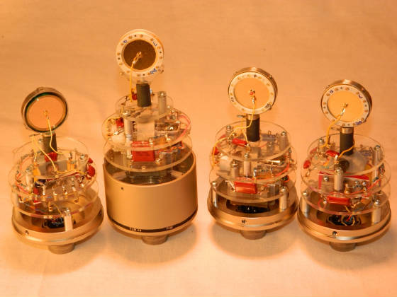
M49a Kit Construction Guide
We've sold a number of our M49A kits to folks interested in DIY mic projects. We also have a number of folks who would love to try out this project but are nervous about getting in over their heads. Oliver recently built a couple of mics into kits for friends and family who wanted an M49 but could never afford a vintage one. During this process, he took the following pictures to show step by step instructions on building your own microphone using our AMI M49A kit. Hopefully, folks will find this basic tutorial helpful.
The beauty of the historic M49 comes from the simplicity of its design, as well as the state of the art 1950s electronic. Almost 60 years later, the M49 still sets the standard for microphones in studios, analog and digital alike. Using the M49A kit, you can make a quality microphone for use in your studio with identical or similar sonic characteristics of the historic M49, depending your layout and taste. Plus, your new mic can be a platform for testing your own design ideas down the road. You should read through this whole article before starting your project.
The M49 electronics are an updated version of the TLM49 to M49 conversion. Layout and electronic set up is nearly the same although we did use a few different parts and materials, but for a general feel you might want to check out the TLM49 mod article.
First, you will need to decide the goal of your mic. If you want to have an M49 on your list of microphones to attract clients then you should go buy a historic M49! However, if you’re looking to build a kit to make a great sounding mic in the direction of the historic M49B/C variety for a fraction of the cost then you should read on.
You will need to decide how close you want your mic to be to a classic M49. For example, the historic M49 came with three different tubes, at least 5 different transformers, and several different revisions. Our kits currently are not 100% accurate but a good example of how the average M49 should sound, so if originality is important for your build, you will need to find some additional parts that do not come stock with our current kit.
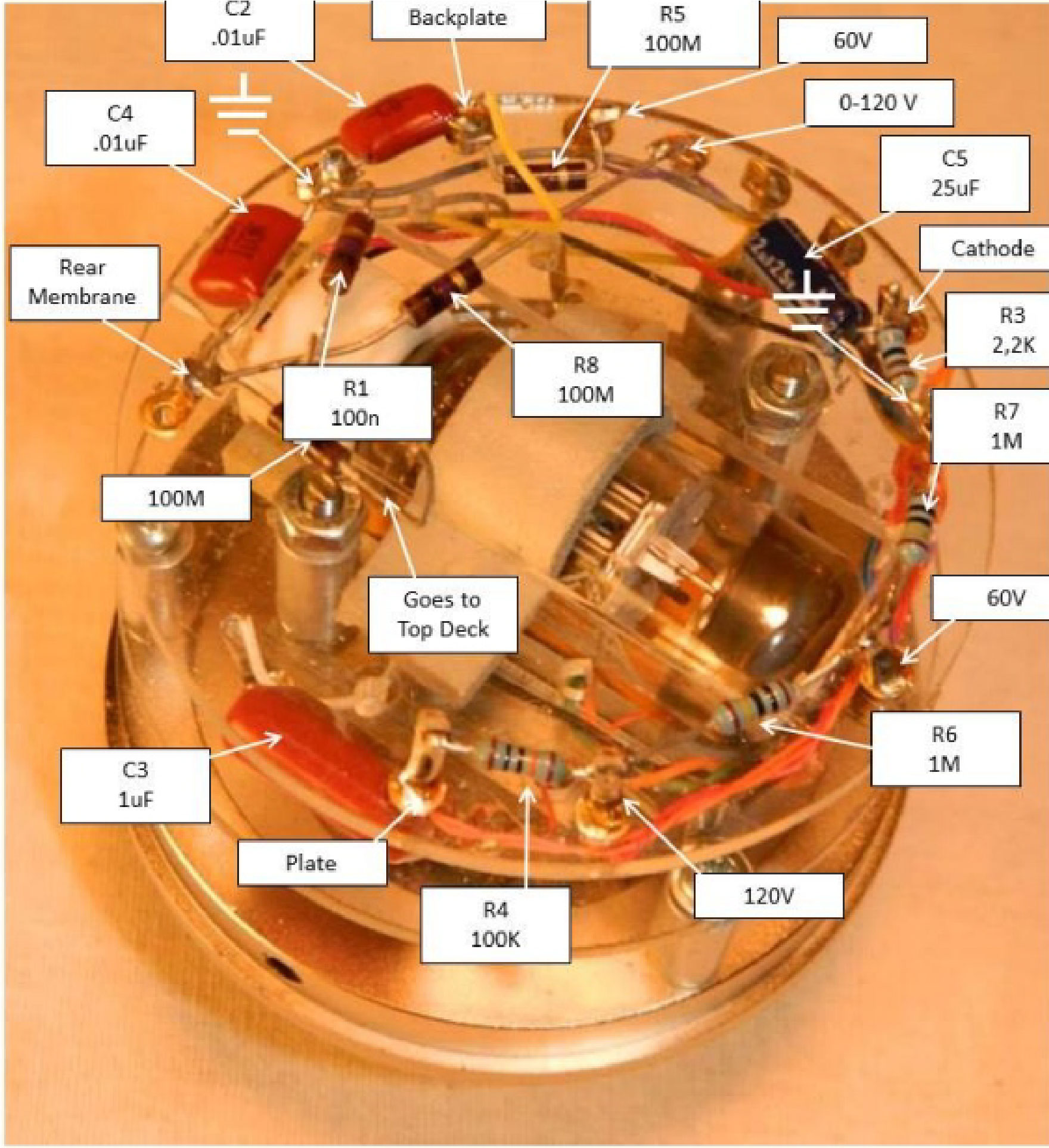
To start, you need to populate the upper plexi assembly. Please do not forget that acrylic glass is very sensitive to heat, so solder fast! The lead wires can be laid out straight, braided, or twisted. It is important that the wire follow exact the rounded stand offs, to insure equal distance to the tube.
As seen on the lower left side of the picture, the second step is to attach the lower plexi board, with the four solder eyelets and the transformer cut out, to the bottom bell. Make sure that you have the board orientated properly so the transformer will sit in the right spot for the next assembly step (check picture). Use the three round stand-off to fasten to the bottom bell. Don't tighten the screws all the way, at least not now.
Close up of the lower transformer board. Note the kit has six transformer mounting holes for either the two or four hole style transformer.
Even though we use materials and parts that look different from the classic M49 design, we kept the layout and foremost geometric position of all parts and components, to insure that the interaction of all parts involved is about the same. The most important part of the classic M49 design is the cable tree, originally held together by a fine twine that is braided around the cable although we use the slightly easier solution - twisting it. In the picture, we use 28AWG silver plated copper in a Teflon sleeve.
The historic NWDR specified the use of a 30AWG stranded copper in a PVC sleeve and the early M49 had a double build silk sleeve. But, it doesn't matter what type of wire you use, just follow the cable tree and pull a tight precise wire from the bottom to the top layer, via the hole right next to the transformer.
After the wire supply strand or wire tree is hooked up and connected to the upper board, the binder audio connector is soldered to the wire tree. Other than on the vintage M49, we decided to have a fixed hookup instead of a rubber mounted hook up. Sure, the rubber would be better for microphonics, but instead of the vintage horse shoe mount, you can order the kit with a weight balanced spider shock mount that will reduce microphonics more than a flexable rubber disk. Please make sure that you leave no more than 1.5 inches when you're done with soldering. In order to install the 7 pin connector, carefully twist up the wire and push it into the 49 bottom bell.
Completed assembly with ac701k


