

Introduction: RGB LED Matrix


Search Instructable, and you can find many LED matrix projects. None of them were quite what I wanted, which was to explore the interactions of hardware and software design to produce something, and produce the final product in a neat PCB with a driver that let's me draw to the "LED screen" using high-level constructs (e.g, drawing a line as opposed to setting specific pixels). This part was important to me, as many of the LED matrix drivers are bare bones and don't provide much in the way of programmatically creating an image or animation. This doesn't mean you can't create images and animations with the other drivers, just that you would have to do more repetitive work from project to project.
So I set out to accomplish my vision. The first step was to design the hardware. This was probably the most challenging for me, as my background is more software. Again, there were many pre-baked designs, and I certainly used them for inspiration, but I wanted to learn through doing, so I prototyped a 4x4 matrix on a breadboard. I learned much through that process, as my first few iterations did not work. But, I did hardware design that worked, which in turn allowed me to start developing a driver.
I chose the Arduino as my driver platform because it is widely available and has plenty of references online. While career experience allowed me to get to a working version of a driver more slickly than my hardware efforts, there was still plenty of iterations while I optimized driver performance for the ATMega micro controller and developed a programming API that I liked.
This Instructuctable documents the design and some key learnings from my project. More information about this project can be found at my website here, including full kits you can purchase to build your own RGB LED matrix.
Step 1: Hardware Design

The primary goal of my hardware design was to create an array of RGB LEDs that I could program, but I also didn't want to spend a lot of money either. The approach I settled on was to use 74HC595 shift registers to control the LEDs. In order to minimize the number of shift registers needed, I arranged the RGB LEDs into an matrix layout where the common anodes were tied together in rows and the red, green, and blue cathode leads were tied together in columns. For the 4x4 matrix, the circuit diagram looked like the attached circuit diagram.
One thing you will note right away is that given the matrix circuit, there are some LED lighting configurations that cannot be done with all the desired LEDs being on at the same time. For example, the matrix cannot simultaneously light two LEDs that are diagonal from each other because powering the both the rows and columns will cause the two opposite LEDs to light on the perpendicular diagonal to the desired LEDs. In order to work around this, we will use multiplexing to scan through each row. There are plenty of resources on the web that cover the technique of multiplexing, I am not going to try to replicate them here.
Since I am using common anode LEDs, that means the rows provide positive power and the columns sink to ground. The good news is that the 74HC595 shift registers can both source and sink power, but the bad news is that they have a limit on how much power they can source or sink. Individual pins of the 74HC595 have a max current draw of 70 mA, but it's best to keep less than 20 mA. The individual colors in our RGB LEDs each have about a 20 mA draw. This means that the 74HC595 can't directly power an entire row of LEDs if I desire to turn them all on.
So instead of powering the row directly, the 74HC595 will instead drive a transistor for each row, and the transistor will switch on or off the current powering the row. Since the design is using a common anode LEDs, the switching transistor will be PNP. If we were using a common cathode LED, the switching transistor would be NPN. Note that with using a PNP transistor to drive a row, the shift register's setting to turn it on now becomes low as a PNP transistor needs a negative voltage between the emitter and base to be turned on, which will allows positive current to flow into the row.
One other thing to consider is the desired bit layout of the shift registers. That is, amongst the shift registers, which bits control which rows or columns in the matrix. The design I sent with is where the first bit, or "most significant bit", sent to the daisy chained shift registers control the column of LEDs red element, the second bit controlled the first column's green element, the third bit controls the first column's blue element, the fourth bit controls the second column's red element, ... this pattern is repeated across the columns left to right. Then the next bit sent controls the last, or bottom, row, the next one the second to last row, ... this repeated until the last bit sent, or "least significant bit", controls the first, or top, row in the matrix.
Finally, I needed to determine what resistors I would use for each of the LEDs in the RGB LED. While you could use the standard formula that combines forward voltage and desired current to calculate the required resistor, I found that setting each LED's current to 20 milliamps resulted in an off-white color when all of the red, green, and blue LEDs were on. So I started to eye-ball it. Too much red in the white meant increasing the red LED's resistor ohms to reduce the current. I repeated swapping out resistors of differing ohms until I found a combination that produced a white color I felt was right. The final combination was 180 Ω for the red LED, 220 Ω for the green LED and 100 Ω for the blue LED.
Step 2: Hardware Construction - Breadboard


The first phase of the hardware constructer was the bread boarding. Here I made a 4x4 matrix with the RGB LEDs. This matrix would require 16 bits to control, 12 for the RGB columns, and 4 for each row. Two 74HC595 shift registers can handle it all. I first researched and designed a circuit I thought would work, then built it on the breadboard.
Probably the biggest challenge of the breadboard build was managing all the wires. I picked up a preformed wire kit for breadboards, but event then it was a little unwieldy. A trick that I found to be helpful was to create a "port" for connecting to the Arduino board. That is, rather than connecting the pins on the Arduino directly to the various IC pins on the breadboard, dedicate a few rows on the breadboard to being the connection point for the Arduino, and then connect the relevant ID pins to those rows. For this project, you only need five connections to the Arduino: +5V, ground, data, clock, and latch.
Once the breadboard build was done, I needed to test it. However, without some sort of driver to send the right signals to the shift registers, I was unable to test to see whether the hardware layout worked.
Step 3: Driver Software Design
Given my own career experience with software development, this was the part of the project that I was probably the most clear about a path to take. I surveyed many of the other Arduino-based LED matrix drivers. While certainly there are good drivers available, none quite had the design I wanted. My design goals of the driver were:
- Provide a high-level API to be able to programmatically create images and animations. Most drivers I saw were more focused on hard-coded images. Also, since I am a C++ programmer by trade, I wanted to use good object oriented design to implement and manage the activities of drawing to the LED matrix.
- Use a double-buffered approach to manage the image on the screen. One buffer is what get programmatically drawn into, while the other represents the state of the matrix pixels at any given moment. The advantage of this approach is that you are not required to completely render the next frame update for the screen in between update cycles of the multiplexing.
- Use PWM to allow more than the seven primitive colors an RGB can render through simple combinations of the red, green, and blue elements.
- Write the driver such that it would "just work" with different size RGB LED matrices that followed my general matrix design approach. Note that while my hardware design uses 74HC595 shift registers, I would expect my driver to work with any shift register style on/off mechanism that is laid out using a similar bit layout as my hardware design. For example, I would expect my driver to work with a hardware design that used DM13A chips to control the columns and a 74HC595 chip to control the rows.
If you want to go straight to looking at the driver code, you may find it on GitHub here.
The first iteration of my driver was a bit of a learning curve on the capabilities of the Arduino platform. The most obvious limitation is the RAM, which is 2K bytes for the Arduino Uno and Nano. Using C++ objects in such a scenario is frequently not advised due to the memory overhead of objects. However, I felt if done right, the benefit of objects in C++ outweighed their cost (in RAM).
The second major challenge was figuring our how to implement the pulse-width modulation via the shift registers so I could generate more than the seven primitive colors of the RGB LED. Having programmed for many years on Linux platforms, I was used to using constructs like threads to manage processes that require consistent timing. The timing of the shift register update operation ends up being pretty critical when making a driver for an LED matrix that use multiplexing. The reason being is that even though the multiplexing is happening so fast that your eyes cannot see the individual LEDs blinking on and off, your ayes can pick up differences in the total aggregate time that any of the LEDs are on. If one row of LEDs is consistently on for a longer period of time than the others, it will look brighter during the multiplexing. This can lead to uneven brightness in the matrix or periodic strobing of the matrix as a whole (this occurs when one update cycle takes longer than the others).
Since I needed a consistent timing mechanism to cause the shift register updates to be consent, but the Arduino doesn't formally support thread, I had to create my own threading-like mechanism. My first iteration of this was to simply to create a loop timer that depended on the Arduino loop() function and would fire an action when a the a certain amount of time has elapsed since the last time the action was fired. This is a form of "cooperative multitasking". Sounds good but in practice this proved to inconsistent when the firing rate was measured in microseconds. The reason for this is that if I had two of these loop timers going, one of their actions frequently took long enough to cause the second action to fire later than desired.
I found that the solution to this problem is to use the Arduino's native clock interrupt mechanism. This mechanism allows you to run a small bit of code at very consistent intervals. So I designed the driver code around the design element of using a clock interrupt to trigger the code for sending the matrix's shift registers the next update in the multiplex cycle. To do this and allow updates to occur to the screen's image to not interfere with an active dump to the shift registers (something we would call a "race condition"), I used an approach of having twin buffers for the shift register bits, one for writing and one for reading. When the user is is updating the matrix image, these operations occur to the write buffer. When those operations are complete, interrupts are temporarily suspended (this means the clock interrupt can't fire) and the write buffer is swapped with the previous read buffer and it is not the new read buffer, then the interprets are re-enabled. Then, when the clock interrupt fires indicating it is time to send the next bit configuration to the shift registers, that information is read from the current read buffer. This way, no writing ever occurs to a buffer that might be currently being read from during a clock interrupt, which could corrupt the information sent to the shift registers.
Designing the rest of the driver was a relatively straightforward case of object oriented design. For example, I created an object to manage the shift register bit image for any given screen state. By encapsulating the code pertaining to the bit image management, creating the aforementioned twin buffers approach was itself an straightforward exercise. But I didn't write this Instructable to extol the virtues of object oriented design. Other design element include the concept of a Glyph and an RGB Image. A Glyph is a basic image construct that has no innate color information. You can think of it as a black and white image. When the Glyph is drawn to the LED screen, color information is given to indicate how the "white" pixels should be colored. A RGB Image is an image where every pixel has it's own color information.
I encourage you to review the Arduino sketch examples and review the driver header documentation to become familiar with how to use the driver to create images and animations on a RGB LED matrix.
Step 4: LED Ghosting


In an LED matrix, "ghosting" is the phenomenon of an LED in the matrix glowing when it isn't desired, usually a very reduced level. My original hardware design was susceptible to ghosting, most notably in the last row. The cause of this is due to two things: transistors do not immediately turn off and parasitic capacitance in the RGB LEDs.
As we scan through the rows, due to the fact that transistors do not immediately turn off, the prior row in the scan cycle is still partially powered when the next row gets turned on. If a given column that was off in the prior row is newly turn on when the new row gets powered, the LED of that column in the prior row will glow for a short bit while that prior row's switching transistor is still in the process of turning off. What causes the transistor to take a noticeable amount of time to turn off is saturation in the base of the transistor. This causes the transistor collector-emiter path to continue to conduct when current is removed from the base, at least until the saturation dissipates. Given that our multiplexing update cycle causes rows to be purposely on for period of time measured in microseconds, the amount of time that the prior row's saturated transistor remains conductive can be a noticeable fraction of that. As a result, your eye can perceive that very tiny amount of time that the prior row's LED is turned on.
To fix the transistor saturation problem, a Schottky diode can be added to the transistor between the base and the collector to cause a little back current to the base when the transistor is on, preventing the transistor from getting saturated. This in turn will cause the transistor to turn off more quickly when current is removed from the base. See this article for an in depth explanation of this effect. As you can see from the picture in this section, without the diode the ghosting is quite noticeable, but adding the diode to the circuit for each row significantly removes the ghosting.
RGB LEDs are susceptible to another phenomenon called parasitic capacitance. The root cause of this is the fact that each of the three color LEDs in the RGB LED unit each have different forward voltages. This difference in forward voltages can cause the effect of electrical capacitance between each of the individual LED colors. Since a electrical charge is built up in the LED unit when powered, when power is removed, the parasitic capacitance needs to be discharged. If the that LED column is otherwise on for another row's powering, the parasitic charge will discharge through that columns LED and cause it to glow briefly. This effect is explain nicely in this article. The solution is to add a discharge path for this parasitic charge other than through the LED itself, and then giving the LED time to discharge before the column is powered again. In my hardware design, this is accomplished by adding a resistor to each row's power line that connects strength to ground. This will cause more current to be drawn with the row is powered, but does provide a discharge path for the parasitic capacitance when the row is not powered.
It is worth noting, however, that in practice I find the effect of parasitic capacitance to be barely noticeable (if you look for it, you can find it), and so I consider adding this extra resistor to be optional. The effect of the slow off time for saturated transistors is a much stronger and noticeable. Nonetheless, if you inspect the three photos provided in this section, you can see that the resistors do completely remove any ghosting that still occurs beyond that of the slow transistor off times.
Step 5: Final Manufacturing and Next Steps
The final phase of this project was for me to create a printed circuit board (PCB). I used the open source program Fritzing to design my PCB. While there was a lot of repetitive tasks to accomplish to layout 100 LEDs on a 10x10 board, I actually found this phase of the project strangely satisfying. Figuring out how each electrical pathway would get laid out was like a puzzle, and solving that puzzle created a sense of accomplishment. Since I am not set up to manufacture the circuit boards, I used one of the many online resources that do small runs of custom PCB. Soldering the parts together was pretty straight forward since my design utilized all through-hole parts.
At the time of writing this Instructable, I have the following plans for my my RGB LED Matrix projects:
- Continue to improve the driver at the API layer to enable more high-level functionality to the programmer, most notably text scrolling.
- Create larger matrix designs, such as 16x16 or even 16x32.
- Explore using MOSFETs instead of BJTs for the row power switching
- Explore using DM13As constant current drivers rather than 74HC595s for the column switching
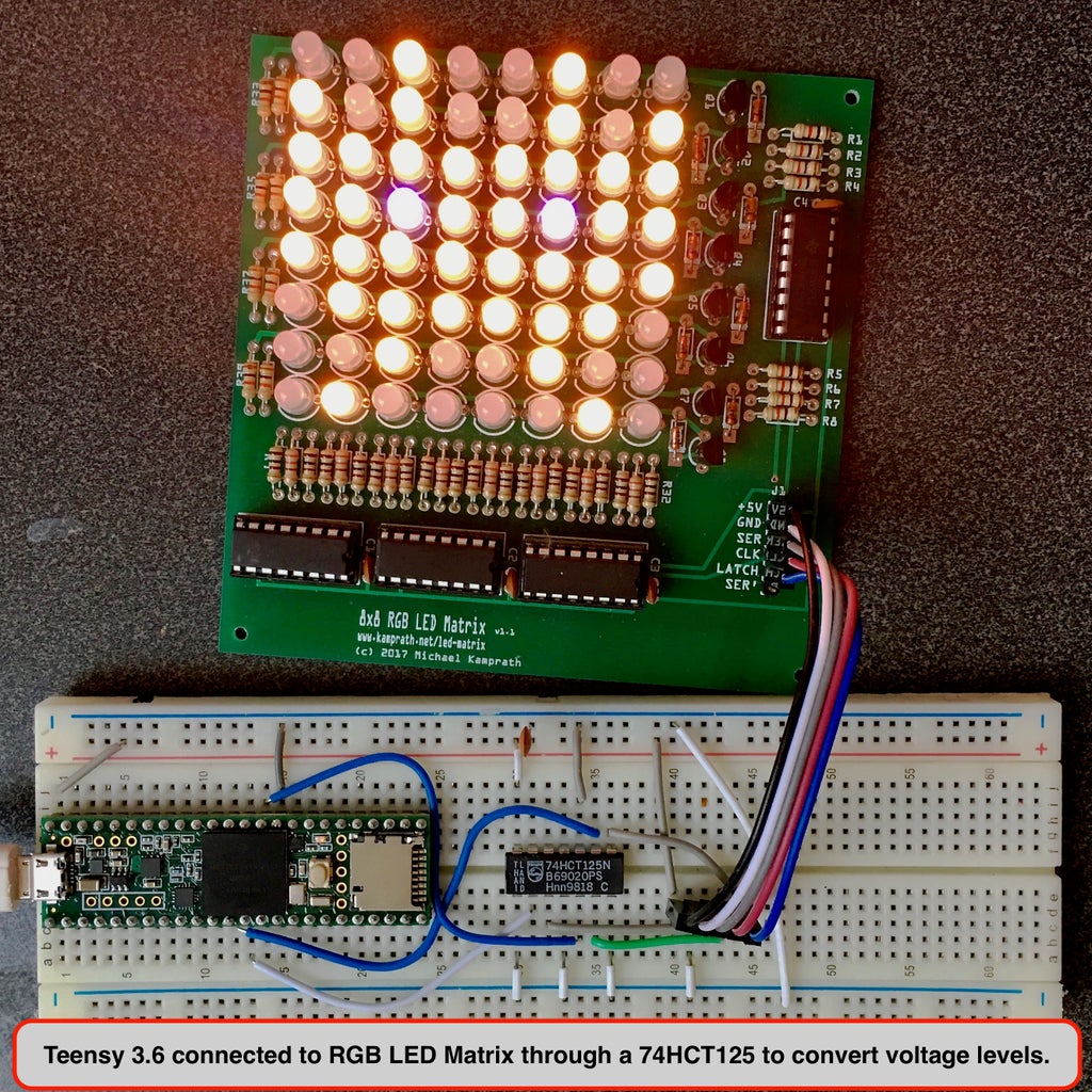
- Create drivers for other micro control platforms, such as the Teensy, ODROID C2, or Raspberry Pi.
Note that both the hardware design and driver have been release under the GPL v3 open source license at this GitHub repository. Furthermore, since even though the PCB manufactures do "small runs" of my PCB design, I still get far more than I personally need. So I am selling full kits for my various RGB LED matrix designs (PCB and all parts included) from my website here.

Participated in the
First Time Author Contest


