

Introduction: LED MATRIX TOUCH CONTROL


This time I’ll share how to integrate touch control into the bi-colors led matrix 16x32. It can be used to control indoor devices via led panel or carry out some interactive effects by touch action. It's great because its operation is accurate and reliable.
To do this, I have added infrared LEDs and the photo-transistors on top and bottom of 16x32 bi-colors led matrix module.
We can see how this led table work by below videos:
TOUCH AUDIO SPECTRUM ANALYZER: It shows music volume unit by using fix FFT transformation. Led panel will be connected to music player by audio jack 3.5mm. During its operation, we can change color of any spectrum frequency bins by touch action:
- LED MATRIX TOUCH CONTROL - TOUCH TOGGLE BUTTONS TEST: This video show the working of 16 x touch toggle buttons on bi-colors led table 16x32.
- LED MATRIX TOUCH CONTROL - CALIBRATION LED TABLE: This video show the calibration process before put this led table in to operation mode.
Step 1: BILL OF MATERIAL
The main components are listed below:
- 01 x Double Sided Printed Prototyping Board 7x9cm (For Aduino Mega shield)
- 01 x Single Side Prototype PCB Circuit Board 18x30cm (For IR Led and Photo-transistor)
- 10 x Decoupling Capacitor 0.1uF
- 80 x R100
- 20 x R150
- 16 x R560
- 16 x R10K
- Female header
Some wires, acrylic plate
Step 2: SCHEMATIC

Picture above is the circuit diagram of the whole project; you can download a high resolution PDF file HERE.
According to the circuit diagram, there are a total of 5 groups as follows:
- Bi-color Matrix 16x32 circuit
It consists of 8 x bi-colors led matrix 8x8 and is arranged into 16 rows and 32 columns.

- Row scanning circuit
It includes the following main components: 8 x 74HC595, 8 x ULN2803, 64 x R100, 8 x decoupling capacitor 0.1uF.
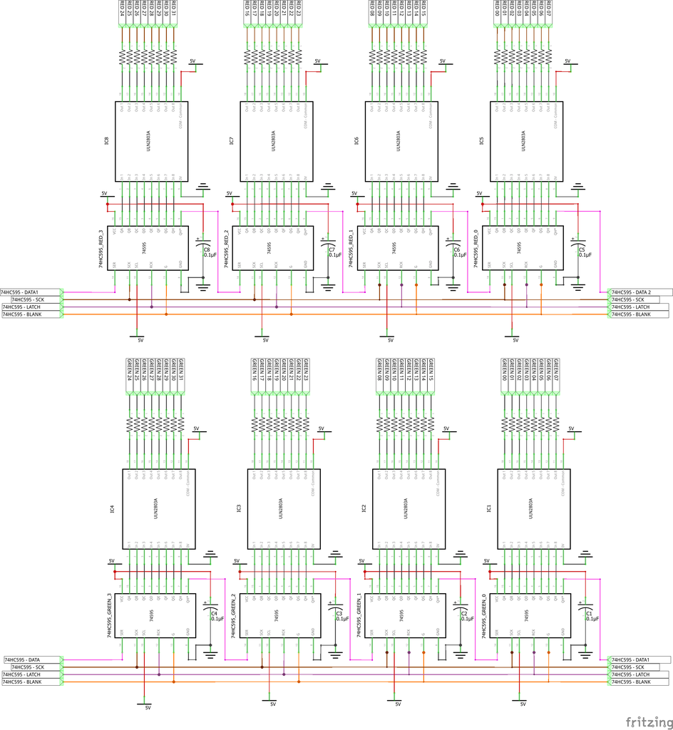
- Column scanning circuit
It includes the following main components: 8 x 74HC138, 16 x Transistor PNP A1013, 16 x R560.

Three printed circuit boards above I made at home by my own. You can buy a full set of 16x32 bi-colors led board, such as:
https://www.ebay.com/itm/16x32-Dot-Matrix-Red-Gree...
- IR Led and photo-transistor circuit
Main components included: 16 x IR Leds, 16 x R150, 16 x Photo-transistors, 16 x R10K, 2 x 74HC4051, 2 x decoupling capacitors 0.1uF.
The 74HC4051 is an 8 channel analog multiplexer / demultiplexer, its working is as follows:
- Multiplexer mode: You can choose between 8 different inputs and select just one you want to read at the time.
- Demultiplexer mode: You can choose between 8 different outputs and select just one you want to write at the time.

- Arduino Mega 2560 shield circuit

Step 3: PCB - ETCHING - SOLDERING CIRCUITS AND ASSEMBLY WORKS
1. You can refer to my topic: https://www.instructables.com/id/HAVE-FUN-WITH-BIC... at STEP 3 for PCB files:
- Bi-color Matrix 16x32 circuit.
- Column scanning circuit.
Row scanning circuit
2. For row scanning circuit, in this project I just used 2 x 74HC138 and 16 x PNP Transistor A1013. It's enough to control 16x32 led board.

The complete LED display board is built by 3 PCBs stacked on each other:
- Bottom layer: row scanning PCB.
- Second layer: column scanning PCB.
- Top layer: Bi-color Matrix 16x32.
Led display board after finishing assembly:

3. IR Led and photo-transistor circuit
Before soldering an infrared transmitter (IR LEDs) and infrared receiver circuit (photo-transistors), we have to adjust the position of IR LEDs and photo-transistors according to the column position of led table. With my index finger, it's just enough to cover two LEDs close together so I design IR LEDs - phototransistors located in the middle of 2 led columns.
The led board has a total of 32 columns so my circuit will have 16 IR LEDs and 16 photo-transistors located opposite each other with position on top and bottom of led panel.
With my tests, photo-transistors should be placed at the top of led board, facing down and IR LEDs should be placed at the bottom of led board, facing up. It will reduce the noise due to daylight affecting the photo-transistor operation.
The picture below will describe my idea for this circuit.

- IR LEDs circuit
Preparing a big single side PCB prototype 18x30 cm and then cut it into small size with dimension about 5x30 cm (keep the original length). Soldering 16 x IR Leds following its schematic on this small PCB.

- Photo-transistor circuit
Cutting single sided PCB prototype with the same size with IR led circuit. Soldering work is little bit more complicated and it need your patience.

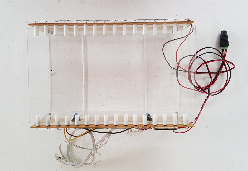
To minimize noises from sunlight or from IR leds placed close together, I have this tip: I cut a white tube with 5mm inner diameter, each piece about 1.5cm length to cover all IR leds and photo-transistors.

It looks like that after covering by tube:

Making a acrylic frame to mount IR LED and photo-transistors circuits on it, paying attention to the alignment so that they are in symmetrical opposite. This acrylic frame will also contain the led matrix board inside, so when we drilled holes to mount all circuits it should be relatively accurate.
4. Arduino Mega Shield circuit
Arduino Mega pins usage is following the below table.

I soldered Arduino Mega shield with some male headers on double sided printed prototyping board 7x9cm.
Making another outer acrylic frame to contain all the circuits inside and mounting Arduino Mega shield outside this frame.
Here's results after soldering and mounting Arduino Mega shield on the outer acrylic frame.

5. Finish
Rearranged and stick decorative sheet for interactive led panel. Done!

Step 4: PROJECT CODING
- Touch control project code is available at my GitHub:
https://github.com/tuenhidiy/LED-MATRIX-TOGGLE-TOU...
In this program, you can use this matrix panel in:
- Interactive mode.
- Touch toggle buttons mode.
2. Touch audio spectrum analyzer code is updated at:
https://github.com/tuenhidiy/TOUCH_AUDIO_SPECTRUM_...
To perform touch audio spectrum analyzer, I used "fix_fft" library: https://github.com/kosme/fix_fft
Led panel (with Arduino - analog input A8) is connected to music player by audio jack 3.5mm. During its operation, we can change color of any spectrum frequency bins by touch action.
We will get different audio spectrum display corresponding to different ADC clock sampling. We can see the Arduino Mega 2560 - ADC clock sampling setting in below table.

For example: With 16 MHz Arduino Mega 2560, the ADC clock with default prescale = 128 (ADC sampling rate 9615Hz), if we discretize frequencies with FFT_N = 64, we will get (9615 /2)/(64/2) = 150hz per frequency bins.
For checking & understanding the operation of audio spectrum analyzer, as well as, FFT transformation, we can go to this website: https://www.szynalski.com/tone-generator/ , then enter the frequency and volume.
More specifically, in my case, I can check at the frequencies of 150Hz, 300, 450, 600, ..., 9600Hz and see what my corresponding led columns look like.
NOTE: In my program, I took an average of 2 contiguous frequency bins, so finally during testing, I checked at the frequencies: 300Hz, 600Hz, 900Hz, ..., 9600Hz.
I have also tested with ADC clock prescale = 32; but in this case, the spectrum analyzer would not be able to show clearly the frequency amplitudes, or Arduino's response will be very slow:
- FFT_N = 064 ==> 600 Hz per frequency bin.
- FFT_N = 128 ==> 300 Hz per frequency bin.
- FFT_N = 256 ==> 150 Hz per frequency bin.
Main touch audio spectrum analyzer program is as below:
void loop()
{
    // Read Analog Input from Microphone with FFT_N = 64
  for (i=0; i < 64; i++)
    {
      val = analogRead(AUDIORIGHT);
      data[i] = val;
      im[i] = 0;
    }
    // Perform the FFT on data for log2(64) = 6
    fix_fft(data,im,6,0);
    for (i=0; i< 32;i++)
    {
      data[i] = sqrt(data[i] * data[i] + im[i] * im[i]);
    }
  // Read Photo-transistors

  if ( (unsigned long) (micros() - samplingtime) > 10  )
    {
      for (IR_counter=0; IR_counter< 8; IR_counter++)
        {
          digitalWrite(IR_Select_C, bitRead(IR_counter, 2));
          digitalWrite(IR_Select_B, bitRead(IR_counter, 1));
          digitalWrite(IR_Select_A, bitRead(IR_counter, 0));
          IR_read_data[0 + IR_counter] = analogRead(A0);
          IR_read_data[8 + IR_counter] = analogRead(A1);
        }
      samplingtime = micros();
    }
  // Counting touch to change the frequency BIN's color of Spectrum Analyzer
  for (byte i=0; i<16; i++)
  {
    if (IR_read_data[i] >= ((IR_calib_high[i] + IR_calib_low[i])/2))
    {
      IR_Read_State[i]=LOW;
    }
    else
    {
      IR_Read_State[i]=HIGH;
    }
      if (IR_Read_State[i] != Last_IR_State[i])
      {
      lastDebounceTime = millis();
      }
    if ((millis() - lastDebounceTime) > debounceDelay)
    {
      if (IR_Read_State[i] != IR_State[i])
        {
          IR_State[i] = IR_Read_State[i];
          // Only increase touch counter by 1 if the new IR_State is HIGH
          if (IR_State[i] == HIGH)
          {
            Touch_Counter[i]++;
          }
        }
      }
  // Show on the LED MATRIX:
  // Average together
  data_average = data[i*2] + data[i*2+ 1];
  // Get color from color-wheel function base on Touch counter and led columns
  get_colour(((Touch_Counter[i]+i)*7) % 127 + 8, &VU_R, &VU_G);
  for (byte yy=0; yy < 16; yy++)
  {
    if ((yy > data_average + 1))
      {
        LED(2*i, yy, 0, 0);
        LED(2*i+1, yy, 0, 0);
      }
    else
      {
        LED(2*i, yy, VU_R, VU_G);
        LED(2*i+1, yy, VU_R, VU_G);
      }
    }
    // Save the reading. Next time through the loop, it'll be the Last_IR_State:
    Last_IR_State[i] = IR_Read_State[i];
  }
}
Step 5: PROGRAMMING EXPLANATION
Hereafter, I will focus on explaining how the touch toggle buttons work:
For touch action working correctly, firstly we have to calibrate the led board in 2 modes:
- High - Calibration: Leave the led panel freely in 5 seconds so that the photo-transistor can read IR leds in no-touch mode. All data of high calibration will be stored in array "IR_calib_high".
- Low - Calibration: Cover all photo-transistors in 5 seconds, this time is simulated as if a touch operation is in taking place. All data of low calibration will be stored in array "IR_calib_low".
The instruction message will be shown on matrix panel during calibration process.
void Calib_High()
{
  for (IR_counter=0; IR_counter< 8; IR_counter++)
  {
  digitalWrite(IR_Select_C, bitRead(IR_counter, 2));
  digitalWrite(IR_Select_B, bitRead(IR_counter, 1));
  digitalWrite(IR_Select_A, bitRead(IR_counter, 0));
  delay(20);
  // Read phototransistors and store data into calibration HIGH array
  IR_calib_high[0 + IR_counter] = analogRead(A0);
  delay(20);
  IR_calib_high[8 + IR_counter] = analogRead(A1);
  delay(20);
  }
  // Print on Serial Port
  for (byte i=0; i<16; i++)
  {
    Serial.print("IR_calib_high[");
    Serial.print(i);
    Serial.print("] = ");
    Serial.print(IR_calib_high[i]);
    Serial.print(" ;");
    Serial.println("");
  }
}
void Calib_Low()
{
  for (IR_counter=0; IR_counter< 8; IR_counter++)
  {
  digitalWrite(IR_Select_C, bitRead(IR_counter, 2));
  digitalWrite(IR_Select_B, bitRead(IR_counter, 1));
  digitalWrite(IR_Select_A, bitRead(IR_counter, 0));
  delay(20);
  // Read phototransistors and store data into calibration LOW array
  IR_calib_low[0 + IR_counter] = analogRead(A0);
  delay(20);
  IR_calib_low[8 + IR_counter] = analogRead(A1);
  delay(20);
  }
  // Print on Serial Port
  for (byte i=0; i<16; i++)
  {
    Serial.print("IR_calib_low[");
    Serial.print(i);
    Serial.print("] = ");
    Serial.print(IR_calib_low[i]);
    Serial.print(" ;");
    Serial.println("");
  }
}
During calibration process carrying out, we open Serial Port in Arduino IDE then copy all printed data into the program. The purpose of this work is that we no need to re-calibrate in the future when the led board has been placed in a fixed location. The printed values shown on Serial Port is as picture below:

In addition, we need to pay attention to the operation of led board at daytime or nighttime. We can see the difference when calibration process is done on the daytime or nighttime through the following table:

You can see below video for calibration work:
After the calibration process, the led board will enter the main operating mode. Now, two channels A0, A1 of Arduino Mega will continuously read values of 16 photo-transistors via 2 x 74HC4051 - 8 channels analog mux/ demux and finally store reading values in array "IR_read_data".
If you want to debug the program or see how photo-transistors work, you can print out the values on Serial Port. But it will slow down all operation of led board.
void Read_Phototransistor()
{
    for (IR_counter=0; IR_counter< 8; IR_counter++)
    {
      digitalWrite(IR_Select_C, bitRead(IR_counter, 2));
      digitalWrite(IR_Select_B, bitRead(IR_counter, 1));
      digitalWrite(IR_Select_A, bitRead(IR_counter, 0));
      IR_read_data[0 + IR_counter] = analogRead(A0);
      IR_read_data[8 + IR_counter] = analogRead(A1);
    }
 if (IR_PRINT)
 {
  // Print on Serial Port if you want to see the working IR value
  // It will slow down your reading IR value
  for (byte i=0; i<16; i++)
  {
    Serial.print("IR_read_data_");
    Serial.print(i);
    Serial.print("---");
    Serial.print(IR_read_data[i]);
    Serial.println("");
  }
 }
}
The below program will update the states of photo-transistors and turn working of led table into 16 x touch toggle buttons. These photo-transistors are sensitive with light, it often generate spurious open/close transitions when touch actions are pressed: these transitions may be read as multiple presses in a very short time fooling the program.
This program uses the millis() function to keep track of the time passed since any touch buttons were pressed. We can adjust the parameter "debounceDelay" until touch actions works precisely and reliably. In my case, "debounceDelay" value is 30 milliseconds.
void Led_Button()
{
  for (byte i=0; i<16; i++)
  {
    // Read the state of the IR photo-transistors into a local variable:
    // Comparing with average of IR_calib_low and IR_calib_high
    if (IR_read_data[i] >= ((IR_calib_high[i] + IR_calib_low[i])/2))
    {
      IR_Read_State[i]=LOW;
    }
    else
    {
      IR_Read_State[i]=HIGH;
    }
    if (IR_Read_State[i] != Last_IR_State[i])
    {
    lastDebounceTime = millis();
    }
    if ((millis() - lastDebounceTime) > debounceDelay)
    {
      if (IR_Read_State[i] != IR_State[i])
      {
      IR_State[i] = IR_Read_State[i];
        if (IR_State[i] == HIGH)
        {
        Control_State[i] = !Control_State[i];
        }
      }
    }
    // Show on the LED MATRIX:
    for (byte yy=0; yy < 16; yy++)
    {
      if (Control_State[i])
      {
        LED(2*i, yy, 15, 0);
        LED(2*i+1, yy, 15, 0);
        }
        else
        {
        LED(2*i, yy, 0, 15);
        LED(2*i+1, yy, 0, 15);
        }
      }
      // Save the reading. Next time through the loop, it'll be the Last_IR_State:
      Last_IR_State[i] = IR_Read_State[i];
  }
}
Two columns of the led panel will be switched from green color to red color and vice versa when we touch the positions that close to photo-transistors and in middle of corresponding two led columns above.
The Arduino Mega 2560 has a lot of outputs, so we can use this led board to control devices, such as 16 x relays for example.
Step 6: FINISH


Above are some pictures taken during my implementation of this project.
Logically, if we add 8 IR leds and 8 photo-transistor placing opposite each other, along the row of this led board and then we can interact with each group of the 4 leds when touch action happens. I think I would try this idea in a recent day.
THANK FOR YOUR READING !!!

Participated in the
Indoor Lighting Contest


