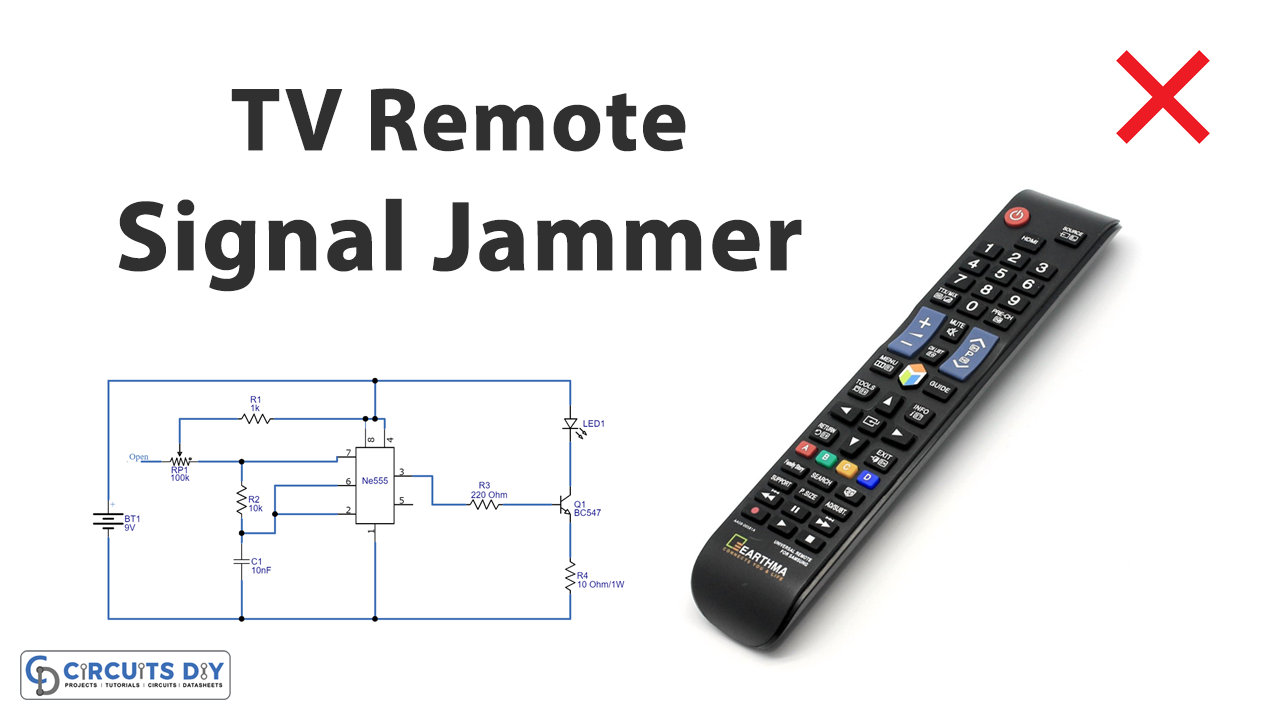
In this tutorial, we are going to make a “TV Remote Signal Jammer Circuit”.
The TV remote signal jammer circuit stops the working of the TV remote, it blocks the communication established between the TV and the remote control. The communication between the TV and remote control is take place due to IR (Infrared) signals. IR light signals are convenient and cannot be disturbed by environmental lights also it has a narrowband and is easy to use in target-based communications.
Here we design a simple TV remote signal jammer circuit by using a timer IC 555 and IR LED. This circuit confuses the IR receiver on the TV by producing a constant signal. This interferes with the remote-control signal. Once you switch on the circuit the TV will not be able to receive any signal from the remote. So basically, this circuit is an IR jammer circuit, by using this handy IR remote we control television things.
Hardware Required
| S.no | Component | Value | Qty |
|---|---|---|---|
| 1. | Transistor | BC547 | 1 |
| 2. | IC | NE555 Timer | 1 |
| 3. | IR LED | – | 1 |
| 4. | Resistor | 1KΩ, 10KΩ, 10Ω/1w | 1,1,1 |
| 5. | Variable Resistor | 100KΩ | 1 |
| 6. | Capacitor | 10nF | 1 |
| 7. | Connecting Wires | – | – |
| 8. | Battery | 9V | 1 |
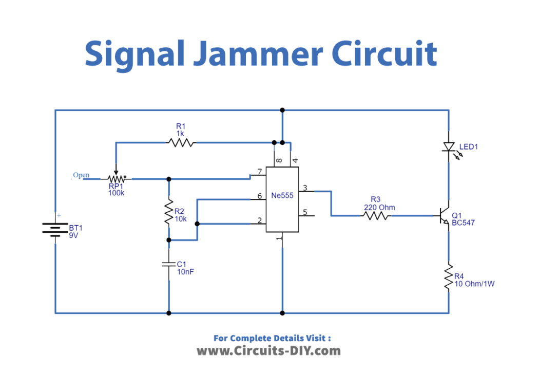
Circuit Diagram
Before understanding the working of this circuit let’s refresh little info about Infrared light and TV Remote signal.
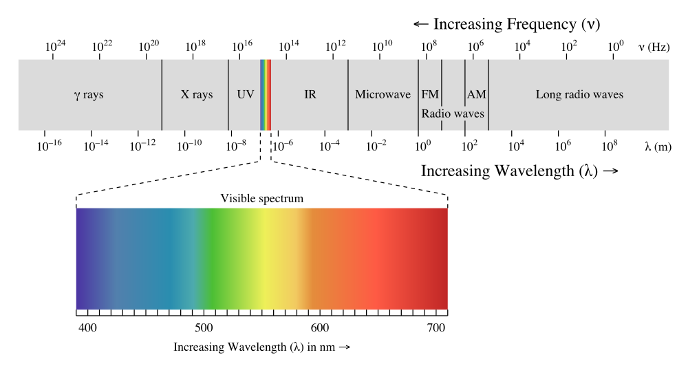
Infrared Light
A small portion of the electromagnetic spectrum is called IR (infrared). Infrared is the frequency of light that is not visible to the eyes. The frequency of the waves lies between three hundred gigacycles to four hundred THz. In this, the radiation is in the region of the electromagnetic spectrum. It has longer wavelengths than visible light. Hence it cannot be a see-through naked eye, it can be in 700nm to 1-millimeter wavelength. Its wavelength is longer than visible light but shorter than radio waves. Infrared could be a communication medium whose properties are considerably totally different from those of radio frequencies. The necessary property of infrared is that it cannot penetrate through walls. Which suggests that it is often simply contained inside a space. Because of this property, infrared is often used in a way that reduces interference and the chance of reprocessing a similar band in numerous rooms. Another advantage of infrared communication is that the massive information measure that is offered to be used, however, has not been exploited to its full extent.
TV Remote Signal
The TV consists of an IR receiver that receives blinking pulses and decodes them for appropriate response. These IR pulses by remote control cannot be detected by the human eye. These pulses can be captured by a camera, as the camera can pick up these pulses. A typical TV IR Remote transmits an IR signal with a start code, Field, address and command these are varies depends on the buttons of the remote. Every TV remote with the button will have a unique code in HEX and it is transmitted through IR LED to the TV set. There will be an IR receiver placed inside the TV and it receives & decode with help of demodulator and microcontroller circuits and then do the necessary tasks. When the infrared receiver on the TV picks up the signal from the remote and verifies from the address code that it’s supposed to carry out this command, it converts the light pulses back into the electrical signal for 001 0010. It then passes this signal to the microprocessor, which goes about increasing the volume. The “stop” command tells the microprocessor it can stop increasing the volume. Infrared remotes have a range of only about 30 feet (10 meters), and they require line-of-sight. This means the infrared signal won’t transmit through walls or around corners, you need a straight line to the device you’re trying to control. You can control different home appliances with different remote buttons by using Arduino Universal Remote.
Working Explanation
In this circuit, IC 555 acts as an astable multivibrator and it will genera a square pulse in the range of 32 KHz – 40KHz, which can be adjusted by using VR1. Most TV set uses 38 KHz frequency. Timer IC here is designed to generate a 38 KHz square wave. We design a circuit in a way that sends the pulses continuously. Because of these continuous pulses, the receiver cannot pick up the intervals sent by the TV remote control, and the intervals of the remote are overlapped and the receiver reads ONE always. Simply speaking we are going to induce a lot of noise into the IR signal, for the receiver to completely read errors all the time. So, when produces square wave connected to IR LED, the LED generates pulses at the same frequency. The potentiometer in the circuit must be adjusted to get the correct frequency. For TV remote communication and producing only carrier at 38 KHz by using this circuit will divert the TV set from receiving the TV Remote signal. Here the timer output is given to the transistor to drive the IR LED. The pulses by jammer LED here overlap the communication intervals between the remote and TV. So, the TV reads always HIGH or ONE when the jammer is ON. Because of this, there will be no communication between the transmitter and receiver. This way we can block the TV remote communication. This circuit IR LED should face toward the TV and should be placed near the TV.
Applications
Can be used in TV remotes.